Wednesday 6 December 2023

Navigating Seamless Change Management with SOLIDWORKS PDM

    In the realm of product design and development, change is a constant. Whether driven by evolving requirements, customer feedback, or compliance updates, managing changes efficiently is crucial for maintaining product integrity and meeting project timelines. SOLIDWORKS PDM (Product Data Management) stands as a robust solution in the realm of change management, offering organizations a streamlined and organized approach to handle modifications throughout the product lifecycle.

Understanding Change Management:

    Change management involves the systematic approach to dealing with changes to a product's design, documentation, or associated data. Effective change management ensures that modifications are controlled, documented, and implemented without disrupting the overall product development process.

Challenges in Traditional Change Management:

    Traditional change management often involved manual processes, document revisions, and complex workflows that could be prone to errors and delays. As product designs became more intricate and the need for collaboration increased, these manual methods proved to be insufficient.


SOLIDWORKS PDM: A Catalyst for Efficient Change Management -

    SOLIDWORKS PDM provides a comprehensive set of tools specifically designed to address the challenges of change management. Let's explore some key features that make it an invaluable asset in navigating change seamlessly:

1. 


1. Centralized Data Management: SOLIDWORKS PDM serves as a centralized vault for storing and managing all design and project-related data. This ensures that all stakeholders access the latest and most accurate information, eliminating the risk of using outdated or incorrect data during the change process.


2. Version Control and Revision Management: The system automates version control and revision management, ensuring that every change is tracked and documented. This capability is crucial for maintaining a clear audit trail and understanding the evolution of a design over time.


1. 3. Automated Workflows: SOLIDWORKS PDM allows organizations to define and customize change workflows. This includes the ability to create, review, and approve change requests seamlessly. Automated workflows reduce the likelihood of errors and speed up the change management process.


 4. Integrated Collaboration: The integration of SOLIDWORKS PDM with SOLIDWORKS CAD software fosters seamless collaboration between design and data management. Engineers can initiate change requests directly from CAD environment, ensuring that changes are accurately reflected in the design data.


1. 5. Access Control and Security: SOLIDWORKS PDM provides robust access control and security features, ensuring that only authorized personnel can make changes or access specific data. This is crucial for maintaining data integrity and compliance with industry regulations.


6. Real-time Notifications and Alerts: Users can set up real-time notifications and alerts within SOLIDWORKS PDM to keep stakeholders informed about the status of change requests. This promotes transparency and ensures that everyone involved in the process is aware of critical milestones.


    In the fast-paced world of product development, an effective change management strategy is a cornerstone of success. SOLIDWORKS PDM offers a comprehensive and integrated solution, enabling organizations to navigate changes seamlessly while maintaining data integrity and collaboration efficiency. By centralizing data, automating workflows, and integrating with SOLIDWORKS CAD, SOLIDWORKS PDM empowers teams to embrace change as an opportunity for growth and improvement rather than a hurdle to overcome. As businesses continue to innovate and evolve, SOLIDWORKS PDM remains a critical tool in achieving efficient and effective change management in the world of product design and development.


Friday 25 August 2023

Creating a Custom Forming Tool

Forming Tools act as Dies that bend, stretch, or otherwise deform sheet metal. The face to which you apply the forming tool corresponds to the stopping surface of the tool itself. By default, the tool travels inward towards the face.

When you create a forming tool:

The locating sketch is added to position the forming tool on the sheet metal part. The colors are applied to distinguish the Stopping Face from the Faces to Remove.

Consider how the minimum radius of curvature (MRC) correlates with the forming tool. The MRC in a forming tool is a good measure of the maximum thickness for a sheet metal part. Beyond this limit, the results are not guaranteed to work. You can verify the MRC in Tools > Evaluate > Check.

In the Check Entity dialog box, under Check for, select Minimum radius of curvature, and click Check.

Creating a Custom Forming Tool:

Forming Tool is saved to a “sldftp” file type. Selections are made to determine the Stopping face and optionally Face(s) to Remove.

Steps To Create a Forming Tool:

A. Geometry Creation:

1. Create a New part that represents the shape of the form you wish to make.; Here we have created a part with basic features: Extruded Boss/Base and Fillet features.

Note: Multi-body parts are not supported for sheet metal forming tools.

2. Here we need a hole; With the help of a split line, the sketch divides the selected face into separate faces.

Once you have finished creating a single-bodied part, select the Forming Tool option from the Sheet Metal toolbar. It can also be accessed from

Insert →Sheet Metal →Forming Tool


B. Forming Tool Feature:

3. The first selection is the Stopping Face (blue planar face). Any faces in front of the stopping face will create the "form" in the sheet metal part.

4. You can also choose Faces to Remove (pink planar face). The selected faces here will leave holes in the sheet metal part when the form tool is applied.

Note:

Stopping Face: Sets the face to define where the forming tool stops when it is applied to the target part. It defines how deep the tool is pushed into the part.


Faces to Remove: Sets the face or faces to remove from the target part. When you place the forming tool on the target part, the faces that you select for Faces to Remove are deleted from the part. If you do not want to remove any faces, do not select any faces for Faces to Remove.

At this point, the form tool has been successfully created. But how do we apply it to parts? Our next step is to add it to our Design Library for easy access while designing in sheet metal parts.

C. Adding Tool to Design Library

The design library is an area to store commonly used features, blocks, etc.

5. To add the forming tool, right-click on your part at the top level in the Feature Manager design tree and select Add to Library.


6. The Add to Library will appear on the Property Manager, and you can able to choose the folder you want to place it in. It is important to put it inside the Forming Tools folder for it to function correctly.


D. Using the Forming Tool from the Design Library

7. Drag and drop the created forming tool from the Design Library; Position the tool according to the requirement (In the Type Tab, you can able to align the tool, rotation angle, select configurations, etc.; In the Position Tab, you can able to constrain the position of the tool for your requirement. Once the forming tool is applied, the intended forming process will take place resulting in the desired output.

8. Results...


*** Thanks for reading *** 

Stay tuned for other tips and tricks or tutorial updates!!!

Saturday 29 July 2023

Linking Materials and Sheet Metal Parameters in SOLIDWORKS

Sheet Metal features in SOLIDWORKS have always been user-friendly. They’ve always been consistent. Also, whenever there is an enhancement to the core Sheet Metal Features, it’s always something useful.

Materials in Sheet Metal are extremely important. If you are choosing between building a part out of Aluminum or Stainless Steel – you aren’t just choosing a material. You’re choosing tooling, bend radius values, and a plethora of other design requirements that are unique to your company. SOLIDWORKS  now allows you to link typical Sheet Metal Parameters to any custom material, so you can use those parameters again and again.

To link a parameter to a Custom Material to a Sheet Metal part, all you have to do is edit that Material – and expand to the Sheet Metal tab.

When you assign a custom material to a sheet metal part, you can link the sheet metal parameters to the material. If you change the material, the sheet metal parameters also update.

To link materials and sheet metal parameters:

1. Open a sheet metal part.

2. In the Feature Manager design tree, right-click Material and click Edit Material.

3. In the dialog box:

a) Right-click Custom Materials and click New Category.

b) Right-click New Category and click New Material.

c) Set the custom material properties on each tab as required.

d) Click the Sheet Metal tab.

Options on this tab are available for custom materials only.

e) Select Thickness Range.

f) Click Add twice.

g) For each row in the table, set the following:

Thickness ranges must be continuous; there cannot be a gap in the range. For example, you cannot define a range from 0 to 3 and define the next range from 4 to 6 because the range between 3 and 4 is not covered.

h) Click Apply and Close.

                                                         *** Thanks for Reading ***

Thursday 29 June 2023

SOLIDWORKS TECH TIP - A simple way to link properties to SOLIDWORKS drawings

1. Creating custom properties in the part file.

          Open a new part document Click New (Standard toolbar) or File > New. In the dialog box, select “Part” or your standard custom part document.

Then open the “File Properties” using the icon as shown in the below image.


           The properties dialog box is opened, and under the “custom” tab we add the SOLIDWORKS part template file properties.

The first row is provided but it is empty so let us start adding the properties
Start with “Property Name” by drop down it shows a pre-made set of items displayed in the list. I select “Drawn By”.

The second column is the “Type” we need to choose how to display the property I select the “Text” type.

Then move to “Value / Text Expression” Here is where we need to enter who drew the model.

             The Last is the “Evaluated Value” this will be the value shown once the property is called upon.

             Auto Populating Properties like material, and weight have their own Value / Text Expression auto displays what material is added in the model. By selecting the drop-down list on the Value / Text Expression.

For Example: Here, I add some of the common properties used by the ISO standard company as shown in the image.
Finally, click “OK” to add the property.

If we want to add, edit, delete, or change the position of the custom properties list by clicking Edit List on the top right corner of the properties window as shown in the below image.


We can also edit the custom properties list by using Notepad by finding the custom properties file path shown in the Option> System Option> File Location> Custom Property File from the drop-down list as shown on the image.

Then browse to that location and find the properties.txt file and you can easily add, edit, delete, or change the location of the properties list.

Then save the part file as a template file as shown in the image. Once you save the custom template file save it to the local disk other than C: It is best practice because once the system got corrupted or crashed the local disk c: is first got cleared.
So save the part template files (*.prtdot) in a separate local disk it can be safe.

Now need to map the custom template folder to the SOLIDWORKS file location as shown in the image. Option> System Option> File Location> Document Template from the drop-down list and click Add to browse the folder location to add.

It shows a prompt Would you like to make the following changes to your search path? click OK.
Note: If you are in the user login it needs the administrator name and password to make the change.

When you open the new part you need to select that particular document template for your pre-loaded custom properties.

Once you opened the custom part document template it shows all your added custom properties as shown in the below image.
Now we link the part document custom property to the drawing document

2. Link custom properties in part file to drawing file.

Open a new drawing document Click New IMG (Standard toolbar) or File > New. In the dialog box, select “Drawing” or your standard custom drawing document.
There no properties were linked to your drawing document as shown below once you opened the SOLIDWORKS standard sheet format.

Editing drawing sheet format by clicking the sheet format tab on the command manager tabs and then clicking the edit sheet format icon.
You can edit the size of the title block boxes and If needs to insert a company logo you can insert then if the text boxes were needed, click Title Block Field. 
There you can add multiple text boxes for the values, text, or custom properties of the files been added.
When you are in the sheet format editing window you can see the $PRPSHEET followed by the attributes entered or linked to the custom properties as shown in the below image.

            If the $PRPSHEET is used to link the custom properties of the part or assembly file once the model were inserted here.

            When the $PRPRSHEET is not available in some of the fields then we need to add the text boxes and then you can fill them manually or link to the custom properties of the part file or assembly file.

             By clicking the Text box fields it shows the options in Property Manager by clicking the link to the property under the text format it opens the Link to the property window.

               In the Link to Property window select the Model found here radio button and select the desired property under the Property name drop-down list. Then click OK

                Then you can see on the drawing sheet the drawn by name which is selected and updated on the below image for your reference.

                 The below image shows that other text boxes were linked to the custom properties and updated to the drawing files sheet.

                Now, we need to save the drawing sheet format by clicking File>Save Sheet Format as shown on the below image.

                Once the sheet format is saved, we need to map the sheet format folder path by clicking Options> System Option> File Location> Sheet Format(*.slddrt) from the drop-down list and click Add to browse the folder.


                 Now we need to save this drawing file as a drawing document template by clicking File> Save as>Drawing Template(*.drwdot) from the save as type and click save.

Here, I saved the drawing document template to the location where the part document template file is stored location. Also, that folder is already mapped for the document template on SOLIDWORKS.

The below image shows both the part and drawing templates.

             Now open the part document and design one simple model and changed the custom properties in the part document as shown below and saved the part file.

Now I make drawing from the part file and choose the custom drawing document template and place the views of the model on the drawing sheet.
Now you can see the custom properties which are entered on the part file are reflected on the linked properties location on the drawing file as shown in the below image for your reference.

*** Thanks for Reading ***


Wednesday 31 May 2023

Compare your designs with 3DEXPERIENCE App!

 Are you looking for a design comparison? Look no further than the 3DEXPERIENCE Compare app!

With the help of the 3DEXPERIENCE Compare application, we can understand the differences between design structures and properties from anywhere on any device.

In this blog, we present a sneak-peek into using the Compare application to leverage your designing experience.


Thanks for watching the video. 


For more details, call 94454 24704

Mail us at mktg@egs.co.in

Visit us www.egsindia.com


Friday 28 April 2023

How to Create a Customized Template for SolidWorks Inspection?

 A step-by-step guide to creating your own SolidWorks Inspection Template


Thanks for watching the video. 

For more details, call 94454 24704

Mail us at mktg@egs.co.in

Visit us www.egsindia.com

Wednesday 22 March 2023

Why Do CEOs prefer project planner tools?

 The project planner is a role on the 3DEXPERIENCE Platform that helps SOLIDWORKS users and other team members manage their projects.

It promotes team-based planning and connects team members flexibly and collaboratively.

An innovative engine automatically optimizes the schedule to meet critical milestones and delivery dates.


Friday 17 March 2023

Permissions and Access to Content - 3DEXPERIENCE SOLIDWORKS

             The 3DEXPERIENCE platform is a business experience platform that provides Product Lifecycle Management capabilities. It enables you to collaborate with team members to design products and bring them to final release.

         On the 3DEXPERIENCE platform, administrator assigns access & roles to the member that define how you can work with content in your collaborative spaces and tasks.


            Your credentials determine which content is available to you in the 3DEXPERIENCE platform. Credentials are the combination of:

· Collaborative space

· Responsibility


Collaborative space

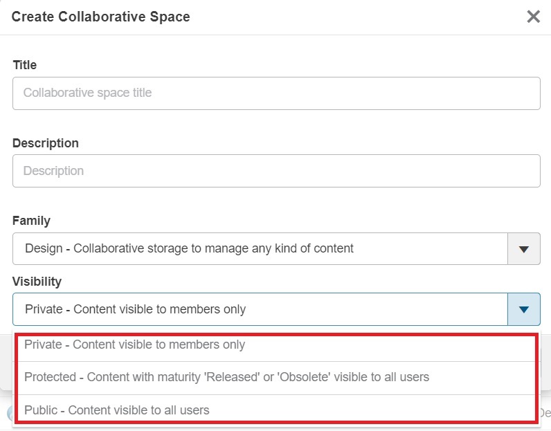
            Collaborative spaces are created to work on a dedicated project and allow multiple users to work in it. Depending on the collaborative space's visibility, you might be able to explore, view, and open the content.

· Public: Content is visible and freely viewed to members of this or any other collaborative space.


· Protected: Content in the Released or Obsolete state is visible to members of this or any other collaborative space. Content in the Private, In Work, or Frozen maturity states is protected.


· Private: Content is accessible only to members of the collaborative space.


Responsibilities

            Responsibilities and permissions for Design tasks in collaborative spaces. Which determines what you can do in the collaborative space.


· Public Reader: Read any content of collaborative spaces that the user is assigned to. Can access Public and Protected collaborative spaces.


· Reader: Can read any content in collaborative spaces that the user is assigned to but not able to evaluate, create or edit content.


· Contributor: Inherits all Reader permissions. Can Create & Evaluation content.


· Author: Inherits all Contributor permissions. Can create Definition content like edit content and take actions such as reserving and unreserving files and changing their maturity level.


· Leader & Owner: Inherits all Author permissions. Can create Resource content such as library, or project template. An Owner can perform administrative tasks such as managing the membership of a collaborative space.