
Friday, 22 May 2015
Thursday, 21 May 2015
Wednesday, 20 May 2015
Thursday, 14 May 2015
HVAC using SolidWorks Flow Simulation

What is HVAC?
HVAC stands for Heating, Ventilation and Air Conditioning. The purpose of HVAC system is to control the Temperature and Moisture of air. Air Handling Units (AHUs) used to cool, heat, humidify, dehumidify, filters and ventilate the air before it distributes to different areas of a building.
Why SolidWorks Flow Simulation HVAC?
HVAC System designer can efficiently and easily evaluate and optimize HVAC Systems with CAD embedded CFD, augmented with the HVAC application module. Designer can ensure Thermal Performance and design Quality at the start and avoid costly rework later on.

How SolidWorks Flow Simulation HVAC helps designer?
- Human Comfort Factors -
calculate eight comfort parameters (including 'Predicted Mean Vote'
[PMV] and 'Predicted Percent Dissatisfied' [PPD]) to measure thermal
comfort and identify potential problem areas
- Advanced Radiation - model
absorption of radiation in solid bodies and definition of the
radiation spectrum for a more accurate radiation simulation
- Tracer Study - analyze the
flow of a certain admixture (Tracer) in the existing carrier fluid
- Enriched Engineering Database - Wide range of building materials and fans to run thermal analysis quickly and efficiently

Applications

Benefits of SolidWorks HVAC Simulation
- Improve HVAC System
Performance
- Maintain Thermal Comfort
conditions
- Maintain optimum Air Quality
- Reduce Energy usage
- Reduce Maintenance Cost
- Remove moisture contents
- Reduce Testing Cost


Thursday, 7 May 2015
Design Validation on Special Purpose Machines (SPM)
Design
validation is the process of ensuring the quality of Designed
product, by conforming to user specifications and requirements.
Special Purpose Machine (SPM) designers and Manufacturers produce
tailor-made machine tools as dictated by their customers. Validation
of these machines fall into two categories - Analytical and Physical.

Analytical
methods include Finite Element Analysis (FEA), Computational Fluid
Dynamics (CFD), Kinematic Analysis of Mechanisms and Free-Body
Diagram. Physical testing include deflection measurements, strain
gauging, vibration testing, measuring fluid flow parameters,
temperature measurement, accelerated durability testing and
frequency response measurements.
Virtual
design validation simplifies the Conventional process and requires
only a 3d CAD Model to validate product's mechanical resistance,
durability, natural frequencies, heat transfer and buckling
instabilities.

SPM
design Challenges:
- Increased design cycle time
- Increased warranty costs and recall
- Re-design
- Material cost
- Product quality and performance
Design
validation on SPM is done to achieve the following :
- Accelerated new product development cycle
- Reduced prototyping costs through Virtual Testing
- Improved product quality and performance
- Ensured reliability and safety standards
- Reduced risk by identifying hotspots in design
- moulding/casting defects identification, weight reduction and load carrying capacity determination
- Vibration reduction in embodiment and other machine modules like pneumatic and hydraulic systems, power packs, etc.,
Design validation benefits:


- Design first time right
- Virtual testing at early stage of
design process
- Reduced time consumption and
costly prototyping
- Design optimization and
alternatives to offset the material cost
- Study different alternatives
- Performance improvement of
complex mechanisms
- Drop testing of handheld
components
- Instant compliance checks for
safety
- Optimized design for size, weight and efficiency
For more info mail us @ lakshmipriya@egs.co.in
Wednesday, 6 May 2015
Are you stuck doing repetitive tasks on your product design?
 In today's competitive market, every product
developer, specifically companies making custom products and high
volume manufactures, want to automate their product design instead of
doing it right from the scratch to shorten the design cycle time and
reduce cost due to manual errors.
In today's competitive market, every product
developer, specifically companies making custom products and high
volume manufactures, want to automate their product design instead of
doing it right from the scratch to shorten the design cycle time and
reduce cost due to manual errors.
SOLIDWORKS 3D CAD provides a fantastic in-built
automation tool, DRIVEWORKS
XPRESS which helps to
automate design task benefiting companies in generating infinite
variations of model using rules based project. Set up the rules once
and run it again and again to get the automated manufacturing drawing
in no matter of time.

SOIDWORKS 3D CAD give designers and engineers
powerful tools to accelerate the development of design variants and
automate repetitive design tasks thereby fastening the design
process, saving time and development costs and increases
productivity.
Monday, 13 April 2015
Tuesday, 31 March 2015
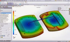
Optimise Plastic Part Design in the initial stages of development
Design plastic parts more efficiently and accurately.
Take the complexity out of getting your injection molds right the VERY first time . In a matter of minutes you can test your designs for possible flaws and defects, eliminating rework of expensive molds and reducing costs.SolidWorks Plastics makes it easy for parts and injection molds. You don’t have to be an expert to easily identify and address companies that design plastic parts or potential defects by making changes to the part or mold design, plastics material, or injection molds to predict and avoid processing parameters, saving resources, time and money.
Manufacturing defects during the earliest stages of design, eliminating costly rework, improving quality, and accelerating time-to- intuitive workflow and design advise to market. Fully integrated with SolidWorks CAD, SolidWorks Plastics works directly on your 3D model, avoiding model conversion issues. You see this intuitive software helps part designers, the impact of design changes right away.
Powerful and fast state of the art meshing covers mold designers and mold makers optimize geometries from thin walled parts to very thick and solid parts. Design for manufacturability without leaving their familiar 3D design experience.

An intuitive interface leads you step by step. Guided analysis, intelligent defaults and automated processes ensure correct setup, even if you rarely use simulation tools.
The SolidWorks Plastics material database contains thousands of commercial plastics and is fully customizable.
- Part designers get rapid feedback on how modifications to wall thickness, gate locations, materials, or geometry can affect the manufacturing of their part.
- while mold designers can quickly optimize multi-cavity and family mold layouts and feed systems including sprues, runners and gates. Analyse and Optimise a range of geometries including thin walled plastic parts.
- The Results Adviser provides practical design advice and troubleshooting tips to help diagnose and solve potential problems. This powerful information gives users tremendous insight into the injection molding process, leading to informed design decisions and better quality products.
While the cost of making changes is low in the early stages of product development, the impact is highest. The sooner you can optimize your plastic parts and injection molds for manufacturability, the better. Design changes in the early stages of product development cost less and have the greatest impact on improving manufacturability.
The cost of change increases substantially further downstream and can lead to significant time-to-market delays. The challenge in plastics part production is determining how your part or mold design impacts manufacturing and how manufacturing will impact your design, and then communicating that information early and often throughout the design to manufacturing process.
SolidWorks Plastics gives you the tools to quickly identify potential problems so you can make changes early in the design process. The most cost effective time to optimize plastic parts for manufacturability is during the initial stages of product design.

Advantages

- Fully embedded in the SolidWorks 3D design environment so you can analyze and modify designs for manufacturability at the same time you optimize for fit, form and function
- Easy to learn, use and does not require extensive analysis or plastics expertise
- Facilitates design team communication: web-based HTML reports make it fast and easy to communicate simulation results and design advice to all members of the design-to-manufacturing team
- Unbalanced filling in family molds can be predicted and avoided with SolidWorks Plastics.
Click the below image for more idea
For Demo on SolidWorks Plastics, mail us @ lakshmipriya@egs.co.in
Tuesday, 17 March 2015
Design for Manufacturing and Assembly using SOLIDWORKS
Design for Manufacturing (DFM) and Assembly (DFA) always has been a challenging proposition when it comes to new product development or cost savings on existing products. At the end of the day, products have to meet the requirements of our end customers.
This presentation is about design for manufacturing and assembly, how we use our CAD tools day-in and day-out, in terms of leveraging on the capabilities of 3D CAD, specifically as addressed by quality requirements. It starts with manufacturing of the individual parts and assembling of the same.
Benefits of DFM and A using SOLIDWORKS
- First time right
- Improved profitability
- Reduced service calls
- Enhance Quality
Monday, 16 March 2015
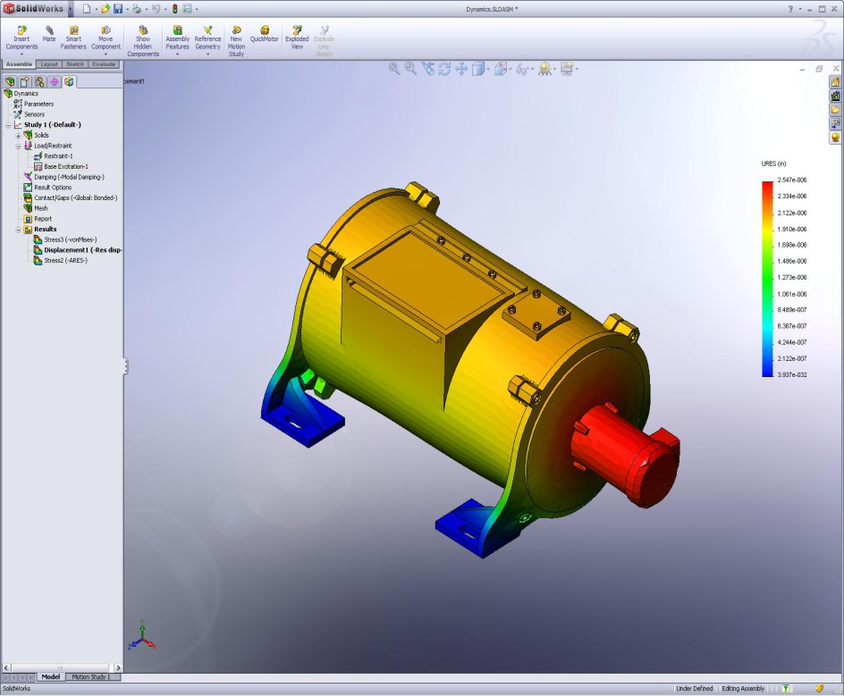
Best Design using SOLIDWORKS SIMULATION Standard
Which design
works best? How do you know you have the best design?
When
it comes to choosing the best design for your project, do you:
- Go with your gut?
- Cross your fingers and hope for the best?
- Methodically test a series of expensive physical prototypes?
Now
there is a better way.
Validate
your designs before Prototype and manufacture Products, with design
validation tools from SolidWorks Simulation.
SolidWorks
Simulation Standard is recently introduced by SolidWorks to enable
every designer and engineer to simulate and analyze their product
performance with fast, easy-to-use CAD-embedded analysis solution. It
will also keep your investment low.
SolidWorks
Simulation Standard can helps you to predict product performance
accurately, while your in design stage itself and
to speedup your design process, innovate faster, and more confident
in the product performance.
SolidWorks Simulation Standard software is used to virtually test your new concepts, develop new designs, and reduce time to market your products. SolidWorks Simulation Standard gives you an intuitive virtual testing environment for linear static Analysis, Kinematic Analysis ( motion ) and fatigue Analysis, so you can answer common engineering challenges with SolidWorks 3D CAD embedded solution.
SolidWorks Simulation Standard software is used to virtually test your new concepts, develop new designs, and reduce time to market your products. SolidWorks Simulation Standard gives you an intuitive virtual testing environment for linear static Analysis, Kinematic Analysis ( motion ) and fatigue Analysis, so you can answer common engineering challenges with SolidWorks 3D CAD embedded solution.
Problems solved using SolidWorks Simulation Standard:
- Weld Failure Elimination
- Analysis-to-test correlations for strains & Deflections
- Deflection and Stress Calculations for Parts and Assemblies
- Durability & Fatigue Life Prediction
- Life Improvement for Equipments
- Kinematic Simulation of Mechanisms
- Factor of Safety Calculations for load combinations
Benefits:
- Development of Cost-effective Designs that meet Durability Targets
- Elimination of Design Failures due to Service Loads
- Leveraging your existing CAD models
- Improve Process Efficiency and Product Effectiveness
- Increase Innovation and Market Share
Wednesday, 11 March 2015
Math behind Style Spline in Solidworks
Whether occurring in nature or in the mind of a designer,
curves and surfaces that are pleasing to the eye are not necessarily
easy to express mathematically. In Solidworks 2014, Solidworks
introduced a new entity called Style
Spline.
I
would like to share
about
mathematical concepts in style spline.

Style
spline is something differs from spline which we are using currently,
Because Spline curve is a
piecewise
cubic curve,
made of pieces of different cubic curves glued together. Style spline
is a Bezier
curve.
A Bezier curve is one of the parametric
curve frequently used in computer
graphics and related fields. But Bezier curves differ from
other types of parametric curves by the type of basis polynomials
used to form them
The
study of these curves was however first developed in 1959 by
mathematician Paul
de Casteljau using de
Casteljau algorithm
at Citroën. The idea of this algorithm is plotting the curve through
repeated linear interpolation by using given control points (P0,
P1,
P2,
P3...
Pn
).
The following discussion will explain how Bezier curve has been
derived mathematically. For an example, Lets we discuss about
methodology of deriving Quadric Bezier curve (i.e. Parabola).
 Generic
Linear interpolation formula between two points P0P1
is
P(u) = (1-u)P0
+ uP1,
for
0
≤ u ≤ 1
Generic
Linear interpolation formula between two points P0P1
is
P(u) = (1-u)P0
+ uP1,
for
0
≤ u ≤ 1
For
better understanding, Lets we take "u" = 0.2, 0.4, 0.6, 0.8
,between the limit 0 to 1

We
know that the value of starting (P0),
control (P1)
and ending (P2)
points. Firstly , we have to do linear interpolation between P0
and
P1
as
well
as
P1
and P2
(for u=0.2), so we get P01
and
P02
points respectively . And again we have to do linear interpolation
between P01
and P02
, finally we will get P(u) point (for u=0.2). So for Quadric Bezier
curve, we need three iteration to find the curve points. We have to
repeat these three iteration with changing value of "u".


Note:
The tangent vector formed by the starting point is tangent to the
curve at point (P0). The derived lines from calculations at every
stage (like P0P1 ) is tangent to the curve at point P(u). Likewise,
Tangency of the curve is controlled.
Lets we see the animation of curve formation in Higher order (4 point) Bezier curve which is created... Click Here
Team EGS
Wednesday, 4 March 2015
DFMXpress turn-rules
Are
you striving to solve your Quality Issues upfront @ the Design Stage?
SOLIDWORKS
3D CAD provides a 3D workspace which showcases your final results
before getting it for production.
As a part of DFMXpress, the analysis tool which helps in upstream validation of difficult areas of manufacturing, following are the set of turn-rules based checks.
Sequencing
with our earlier posts, following are the turn-rules:
1. MINIMUM CORNER RADII FOR
TURNED PARTS
- Avoid sharp inside corners. Provide a generous inside radius to accommodate a tool with a large nose radius, which is less prone to breakage
- A turn-down surface perpendicular to an un-machined (cast) surface might cause burrs
 |
| Minimum corner radii for turned parts |
2. BORE RELIEF FOR TURNED PARTS:
- Provide tool relief for the bottoms of blind bored holes in turning operations.
 |
| Bore relief for turned parts |
Wednesday, 18 February 2015
DFMXpress Injection Molding Rules
Is
your company equipped enough to design your plastic injection mold in
an invariable environment?
It may sound hard. But SOLIDWORKS 3D CAD software allows us to design plastic injection molds with composite geometries. It provides a 3D workspace which showcases our final results before getting it for production. One can also validate the mechanical functionality of the molds and the components which in turn increases your productivity multi-fold.
SolidWorks can handle various CAD data and provides access to a range of add-on mold design and production applications. Cut down your mold design cycle, import and export various data formats and enhance your design communication with your customers, with the help of SolidWorks 3D CAD.
In continuation with our earlier blog posts, following are the injection molding rules-based checks:
- MINIMUM WALL THICKNESS: Walls which are too thin can cause filling problems and develop high molding stresses and also lead to structural failures and poor insulation characteristics. A minimum wall thickness of 2.0 mm is recommended
- MAXIMUM
WALL THICKNESS:
Avoid walls which are too thick to prevent cooling problems and
defects such as sink marks and internal voids. Thick walls can also
increase cycle time
Subscribe to:
Posts (Atom)