Thursday, 3 April 2025

Interference detection in SOLIDWORKS is a tool that helps find overlapping parts in an assembly. It ensures all components fit together correctly and prevents problems during manufacturing or assembly.

How to use in SOLIDWORKS:

Step: 1
➢ Open Your assembly in SOLIDWORKS
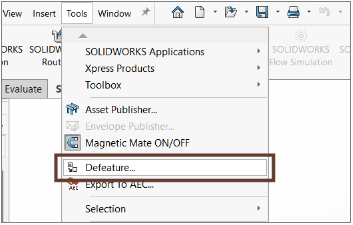
➢ Go to Evaluate Tab > Interference Detection.


Step: 2
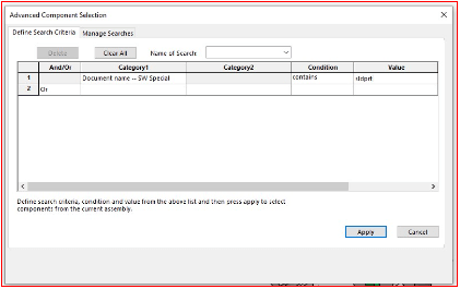
In Selection Components, the top-level assembly is selected by default, or we can manually select specific components


Exclude Components: Excludes specific components from the interference analysis.

Hide Excluded Components from View: Hides the excluded components in the graphics area.


Step: 3
After selecting, the Options group helps to adjust the detection settings.

➢ Treat coincidence as interference: Consider coincident entities as interferences.
➢ Show ignored interferences: Displays ignored interferences in the Results list.
➢ Treat subassemblies as components: Consider subassemblies as single entities, ignoring interferences between their internal components.


➢ Include multibody part interferences: Detects interferences between individual bodies within multibody parts.
➢ Include surface bodies: Identifies interferences involving surface bodies but does not calculate the interference volume.
➢ Make interfering parts transparent: Displays interfering components as transparent for better visualization.
➢ Create fasteners folder: Groups interferences involving fasteners (e.g., nuts and bolts) into a separate folder named “Fasteners.”
➢ Ignore hidden bodies/components: Excludes interferences involving hidden components or bodies within multibody parts.

Step: 4
Once the option settings are checked, click “Calculate”.


In Results:
➢ Displays the detected interferences.
➢ Shows the volume of each interference listed.
➢ Selecting an interference in Results highlights it in red in the graphics area.


Step: 5
These options allow control over the display state of non-interfering components in the assembly.


Contact Us: Have questions or need assistance? Feel free to reach out!

Email: mktg@egs.co.in
Phone: +91 94454 24704


How to Add and Manage Custom Properties in a SOLIDWORKS Part Template?


Open new part document Click New (Standard toolbar) or File > New. In the dialog box, select “Part” or your standard custom part document.

Then open the “File Properties” using the icon as shown in the below image.


The properties dialog box is opened, under the “custom” & “Configuration Properties” tab we add the SOLIDWORKS part template file properties


Adding Properties:

• First row is provided but it is empty so lets start adding the properties
• Start with “Property Name” by drop down it shows a pre-made set of items were displayed in the list. I select “Drawn By”.


• Second column is the “Type” we need to choose how to display the property I select the “Text” type.
• Then move to “Value / Text Expression” here is where we need to enter who drawn the model.
• The Last is the “Evaluated Value” this will be the value shows once the property is called upon.
• Auto Populating Properties like material, weight have their own Value / Text Expression auto displays what material is added in the model. By selecting the drop down list on the Value / Text Expression.


Example: Here, I adds some of the common properties used by the ISO standard company as shown in the image.

Finally click “OK” to add the property.


If we want add, edit, delete or change the position of the custom properties list by click Edit List on the top right corner for the properties window.


We can also edit the custom properties list by using the Notepad by finding the custom properties file path shows in the Option> System Option> File Location> custom Property File from the drop down list.


Then browse to that location and find the properties.txt file and you can easily add, edit, delete or change location of the properties list.


Then save part file as template file, and you can reuse it for upcoming model files without any further delay.


Author: Sakthivel A is an Application Engineer at EGS Computers India Pvt Ltd, specializing in supporting and delivering value-added services to a diverse range of SOLIDWORKS customers for the past 3 years. He excels in understanding customer requirements and providing customized solutions to meet their needs effectively.

Contact Us: Have questions or need assistance? Feel free to reach out!

Email: mktg@egs.co.in
Phone: +91 94454 24704

How to REMOVE INTELLECTUAL PROPERTY FROM SOLIDWORKS FILES

When sharing SOLIDWORKS models externally, it’s often important to keep your design confidential to protect your intellectual property. In this blog, we’ll see the options available for REMOVING INTELLECTUAL PROPERTY FROM SOLIDWORKS files.

1. Defeature:

Defeature is a tool where you can remove details from a part or assembly and save the results to a new file in which the details are replaced by dumb solids (that is, solids without feature definition or history). You can then share the new file without revealing all the design details of the model.

Click Tools pull-down menu > Click Defeature

SOLIDWORKS Defeature

This will then open up a simple 3-step wizard, which will help manage what you want to remove and hide from those spying eyes.

SOLIDWORKS Defeature

The options available will depend on the file type you are working on:

Defeature – Components, Bodies

For assemblies, you can specify components to remove from the model. For multibody parts, you can specify bodies to remove from the model.

Defeature – Motion

If you want to allow motion in an assembly, you can remove details from groups of components and allow motion between the groups.

Defeature – To Keep

In parts and assemblies, you can specify features to retain, such as mounting holes, which might otherwise be removed by the Defeature tool.

Defeature – To Remove

In parts and assemblies, you can specify to remove features that were not automatically removed.

Defeature – Feature Removal Complete

In parts and assemblies, you can save the less-detailed model in a separate part file.

You can see from the images below the before and after effect of Defeature on the same SOLIDWORKS file.

before and after effect of Defeature

Another great advantage of Defeature is when you create CAD neutral formats such as ‘. STEP’ the file size is greatly reduced.

Benefits Of Defeature

  • Find and delete bodies or components – internal and based on relative size.
  • Creates new model.
  • Good way to create less-detailed part from complex imported parts.
2. Save Assembly as a Part (Exterior Surface):

If you need to protect intellectual property of an assembly model, saving it as a part is one of the easiest ways to do this. When saving an assembly as a part, you can direct SOLIDWORKS to save only exterior faces.

To do this, go to File > Save As, then change the Save as type to SOLIDWORKS Part (*.prt; *.sldprt). Under Geometry to save, select Exterior faces, then click the check box for Preserve geometry references and click Save. A part will be saved in the location of your choosing, which will be comprised of outer surfaces only.

SOLIDWORKS Part

The recipient of this model will not be able to use FeatureWorks to build a Feature Tree from the surfaces, ensuring REMOVING INTELLECTUAL PROPERTY FROM SOLIDWORKS effectively.

3. Save Assembly as a Part (STL):

To do this, go to File > Save As, then change the Save as type to SOLIDWORKS Part (*.prt; *.sldprt). Then save the part as an STL file format. This will create separate Graphics Bodies but in a single file. This method is also useful for 3D Printing processes while still REMOVING INTELLECTUAL PROPERTY FROM SOLIDWORKS models.

SOLIDWORKS Part
  1. Publish to eDrawings or 3D PDF:

If you wish to share a file for viewing only, consider saving the file as a 3D PDF, or publish it to eDrawings. Both methods allow you to share your models in a way that the recipient can only open the file in a viewer (with limited measurement capabilities).

  • To publish a file to eDrawings, go to File > Publish to eDrawings.
E drawings
  • If you do not wish to allow the recipient to measure the model in eDrawings, go to Tools > Options > System Options > Export, then change the file format to EDRW/EPRT/EASM and uncheck Okay to measure this eDrawings file.
  • To save the file as a 3D PDF, go to File > Save As then change the Save as type to Adobe Portable Document Format (*.pdf) and click the Save as 3D PDF checkbox.
eDrawing


Author Details: Palaniyappan T is an Elite Application Engineer with a background
in Mechanical Engineering, specializing in customer success. He serves as a Team Lead for Technical Support and also a Customer Success AE, leveraging almost 10 years of experience with SOLIDWORKS CAD, SOLIDWORKS PDM and also with the
3DEXPERIENCE Design Ecosystem. His expertise has enabled him to successfully assist over 100 customers in resolving technical challenges, improving their design workflows, and achieving their goals.

Contact Us: Have questions or need assistance? Feel free to reach out!

Email: mktg@egs.co.in

Phone: +91 94454 24704 

How to Use Advanced Select Options in SOLIDWORKS?

In SOLIDWORKS, when working with large assemblies that include multiple subassemblies, selecting individual components can become a significant challenge. The standard method of selecting components from the Feature Manager design tree can be inefficient, as it often includes subassemblies, making it difficult to isolate and select the desired parts.

This blog will explore the challenges of selecting components in large assemblies and introduce the concept of using a selection tool to streamline the process. By utilizing advanced search techniques, you can efficiently select all parts within an assembly, whether they are in the main assembly or nested within subassemblies. This approach helps improve efficiency, especially when dealing with large and complex assemblies in SOLIDWORKS.

Advanced Select in SOLIDWORKS

SOLIDWORKS allows users to select components based on their properties using the built-in selection options. For example, it offers the ability to select all suppressed parts with a single click. Additionally, users can define custom search criteria by specifying conditions and values and can apply logical “and” or “or” operators between these criteria.


Category 2 can be defined for specific options within Category 1, including custom properties, in-context relations, and file status. When these categories are selected, Category 2 displays the relevant parameters or options that can be used for selection. The available conditions for filtering in SOLIDWORKS include ‘=’, ‘<+’, ‘<‘, ‘>’, ‘>=’, ‘≠’, ‘contains’, ‘is (exactly)’, ‘is not’, ‘is inside’, and ‘is outside’. This flexibility allows for more refined and tailored selections, streamlining the design process.

Refining Component Selection in SOLIDWORKS

In the context of SOLIDWORKS, efficiently selecting specific components within an assembly is crucial for streamlining workflows, especially when applying properties such as materials. A common scenario is the need to select all parts in an assembly while excluding subassemblies. This can be particularly useful when you want to apply material to every part simultaneously.

One effective method to accomplish this is by utilizing SOLIDWORKS’ advanced selection tool. By defining a custom search criterion, such as the “Document Name – SW Special” category, you can refine the selection process. For example, by setting the condition to “contains” and the value to “.sldprt” (the file extension for part files), you can specifically select all part documents within the assembly. This approach ensures that only part files are selected, leaving subassemblies untouched.

SOLIDWORKS

Additionally, SOLIDWORKS allows you to save this custom search as a predefined selection filter. Once saved, you can add it to your list of favorites, making it easily accessible whenever you right-click and need to perform similar selections in the future.

This is just one of the many practical applications of advanced selection techniques in SolidWorks. Whether you’re dealing with large assemblies or complex designs, these tools can be tailored to meet a wide variety of selection needs, improving efficiency and accuracy in your modelling process.

ADVANCE SELECT OPTIONS In SOLIDWORKS

Another commonly used selection option in large assemblies is the ability to select internal components for suppression, which helps improve overall assembly performance in SOLIDWORKS.

SOLIDWORKS

Imagine manually selecting each internal component to suppress them – it could take a lot of time. However, as shown in the performance evaluation tab, we were able to suppress 748 components with just one click, saving a significant amount of time in SOLIDWORKS.

SOLIDWORKS

Thank you for reading! I appreciate your time and hope you found the insights helpful.

Author: Nandhakumaran is an Application Engineer at EGS India, a SOLIDWORKS Value-Added Reseller, with expertise in Dassault Systèmes software across multiple industries. With over 20 certifications in SOLIDWORKS and Dassault Systèms software, He is dedicated to helping clients get the most out of their tools.

Contact Us: Have questions or need assistance? Feel free to reach out!

Email: mktg@egs.co.in
Phone: +91 94454 24704