Wednesday, 16 December 2015
Friday, 11 December 2015
Create Sheet Metal Swept Flanges "Hole" in a better Way
One of the best sheet metal enhancements in SOLIDWORKS 2016 is the ability to add Cut Features to a Swept Flange and have those features map correctly to the Flat Pattern. Although the Swept Flange tool is a wonderful part of the Sheet Metal toolset, I have had many users comment about how frustrated they were that they could add Cut and Hole Features to their Swept Flanges and see them in their formed views but the hole features were missing in their Flat Pattern when it was time to send the part out to the Punch Press or Laser Cutter!

Above is a Sheet Metal part created in SOLIDWORKS 2015, the part is made using a Swept Flange and two Cut features. You can see when the part is flattened the two Cut Features do not propagate to the Flat Pattern and disappear from the view, this would usually result in having to add the Cut Features to the Flat Pattern separately which results in a potential loss in accuracy and adding valuable time to the part design process.

SOLIDWORKS 2016 Sheet Metal Swept Flange Flat Pattern
In the SOLIDWORKS 2016 example above, you can see the same Swept Flange part but with both Cut Features being mapped correctly onto the Flat Pattern and not requiring any features to be added directly to the Flat Pattern. It is easy to see how anyone who uses the sheet metal Swept Flange often will take full advantage of this fantastic enhancement to make the creation of complex sheet metal parts quicker and easier than ever before.
For more info mail us @ lakshmipriya@egs.co.in


SOLIDWORKS 2015 Sheet Metal Swept Flange Flat Pattern
Above is a Sheet Metal part created in SOLIDWORKS 2015, the part is made using a Swept Flange and two Cut features. You can see when the part is flattened the two Cut Features do not propagate to the Flat Pattern and disappear from the view, this would usually result in having to add the Cut Features to the Flat Pattern separately which results in a potential loss in accuracy and adding valuable time to the part design process.

SOLIDWORKS 2016 Sheet Metal Swept Flange Flat Pattern
For more info mail us @ lakshmipriya@egs.co.in
Wednesday, 9 December 2015
Watch Out a New Tool in SOLIDWORKS 2016
To ensure greater accuracy for digital simulation or to produce a 3D printed prototype, it’s often necessary to model the physical threads on shafts and holes, among many other features.
To create a thread in previous versions of SOLIDWORKS, we had to manually create a profile and a helix for creating a swept cut. This process has now been automated with a new Thread tool in SOLIDWORKS 2016. The new Thread tool allow us to create helical threads on cylindrical faces using profile sketches. Now, this feature is very flexible, allowing us to specify the start thread location, an offset, end conditions, the type, size, diameter, pitch and rotation angle, and even choose options like right-hand or left-hand thread.
We can also create our own custom thread profiles like weldment profile. SOLIDWORKS allow us to store our custom thread profile as a library feature. The default location where these are saved can be modified at Tools > Options > System Options > File Locations. Select Thread Profiles from the Show Folders for pull-down menu.

In the Thread Property Manager,
To create a thread in previous versions of SOLIDWORKS, we had to manually create a profile and a helix for creating a swept cut. This process has now been automated with a new Thread tool in SOLIDWORKS 2016. The new Thread tool allow us to create helical threads on cylindrical faces using profile sketches. Now, this feature is very flexible, allowing us to specify the start thread location, an offset, end conditions, the type, size, diameter, pitch and rotation angle, and even choose options like right-hand or left-hand thread.
We can also create our own custom thread profiles like weldment profile. SOLIDWORKS allow us to store our custom thread profile as a library feature. The default location where these are saved can be modified at Tools > Options > System Options > File Locations. Select Thread Profiles from the Show Folders for pull-down menu.

Creating a cut Thread
Click Insert > Features > Thread
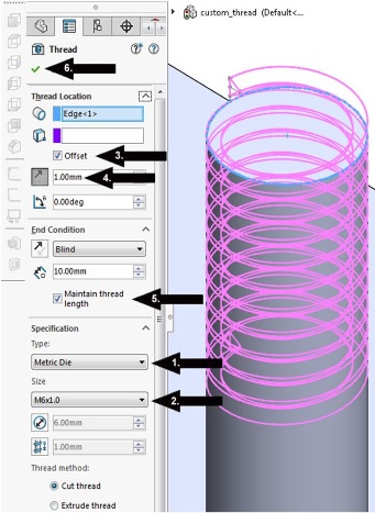
In the Thread Property Manager,
- Under Specification,we can select any type of thread profiles here its metric die.
- Set the Size to M6x1.0.
- Check Offset under Thread Location.
- Set the Offset Distance to 1.00mm and clicked the Reverse Direction button.
- Check Maintain Thread Length under End Condition. Note that when you do this the thread profile updates from 10 to 11 millimeters in length.
- Click OK

Thread is now created and we are ready to move on with designing our part. This new Thread tool in SOLIDWORKS 2016 is a great time saver and we can quickly create all the accuracy and detail we need, while staying focused on design.
For more info mail us @ lakshmipriya@egs.co.in
For more info mail us @ lakshmipriya@egs.co.in
Wednesday, 14 October 2015
Friday, 25 September 2015
OPTIMISING AIR FLOW INSIDE A LIVING ROOM

Living Environment System
A living system should maintain and balance the optimum
room temperature. Heat balance in a living room is very important from the energy
consumption perspective to influence the essential temperature parameters. The purpose
of an air conditioner is to maintain a comfortable indoor environment. The comfort
system is usually determined by a combination of three factors:
-
Temperature
-
Humidity
-
Air distribution

For this reason the main purpose of air conditioners are to:
- Control room temperatures (cooling/heating)
- Control room humidity levels (drying, humidifying)
- Optimise air flow (circulation, distribution)
- Clean Air (filtration)
Introducing HVAC Flow Simulation:
HVAC (Heating, Ventilation and Air Conditioning) is an integrated module inside SolidWorks Flow Simulation. Managing the airflow within a large scale environment is a key to ensure the optimum temperature is maintained for the largest number of people possible. The HVAC design module present inside SolidWorks Flow Simulation gives the user with great tools to tackle the tough challenges in design efficient cooling systems for people and large scale environments. The HVAC Module not only simulates the airflow in the environment but also for the products within the environment. With the enhanced tools designers can now analyse products considering more real world behaviours.
HVAC (Heating, Ventilation and Air Conditioning) is an integrated module inside SolidWorks Flow Simulation. Managing the airflow within a large scale environment is a key to ensure the optimum temperature is maintained for the largest number of people possible. The HVAC design module present inside SolidWorks Flow Simulation gives the user with great tools to tackle the tough challenges in design efficient cooling systems for people and large scale environments. The HVAC Module not only simulates the airflow in the environment but also for the products within the environment. With the enhanced tools designers can now analyse products considering more real world behaviours.

The objective to design any living room is to provide comfortness for the people inside a living room. HVAC module provides specific tools to support the user to design air conditioning or large scale cooling equipment with ease of use. The effectiveness of environment control is measured by the human comfort parameters. The following are the comfort parameters:
- Predicted Mean Vote (PMV)
- Predicted Percent Dissatisfied (PPD)
- Operative Temperature (K)
- Draft Temperature (K)
- Air Diffusion Performance Index (ADPI)
- Local Air Quality Index (LAQI) for fluids
- Contaminant Removal Effectiveness (CRE) for fluids
- Flow Angle

The impact of the thermal radiation from the sun towards the environments seems to be more complicated and also requires cooling effects. The engineering database inside the SolidWorks Flow Simulation includes wide range of building materials & fans. The material database provides the user to select materials to perform thermal analysis in a quicker and efficient manner. This helps the user to understand the impact of material choices for radiation modelling in HVAC module.
- HVAC helps design engineers to quickly and accurately
model complex air conditioning and cooling systems for thermal analysis.
- Provides the exact visualisation of the air flow
inside a room.
- Helps to find the temperature distribution along
the areas present inside the room.
- Easy use of industry specific tools enables the
HVAC designer for better productivity and perform enhanced simulation for working
and living conditions.


Wednesday, 23 September 2015
MySolidWorks Professional Promotion Ending Soon
MySolidWorks Professional adds tremendous value to thousands of SOLIDWORKS subscription customers worldwide with access to over 500 online training videos and SOLIDWORKS certification prep courses introducing new skills to help you become more productive.
In addition to the existing training content, such as SOLIDWORKS Essentials, Advanced Part Modeling, Assembly Modeling, Electrical Design or Sheet Metal Design, we’ve recently added a few new topic areas including Simulation, Model-Based Definition (MBD), Enterprise PDM and Industrial Designer. Here is just a sample of the new training sessions you can take advantage of through MySolidWorks Professional:
SOLIDWORKS Simulation – Discover the SOLIDWORKS Simulation product suite.

SOLIDWORKS MDB – This module is a SOLIDWORKS MBD overview. It covers the process of defining a model in 3D, capturing 3D Views and publishing a 3D PDF and eDrawings file.

EPDM – An overview of the Enterprise PDM data management solution and functionality.

SOLIDWORKS Industrial Designer – Review these lessons to learn how to use 3DEXPERIENCE Platform tools.

SOLIDWORKS Certification Prep Courses – Review these sessions to prepare for the CSWA, CSWP and CSWE exams.

MySolidWorks Professional is available at no cost to our subscription paying customers until the end of October. So take advantage of this offer and start accessing 500+ online training sessions. Contact your reseller today to learn more about how to get access to MySolidWorks Professional.

Monday, 14 September 2015
SOLIDWORKS 2016
MAKE GREAT DESIGN HAPPEN
SOLIDWORKS
is about to release a new version of its flagship product in terms of
innovation and improved functionalities with the roll-out of
SOLIDWORKS 2016 by September
22, 2015. Solidworks
2016 comes with all the exciting new features and enhancements that
are eagerly awaited by the customers.
With
SolidWorks 2016, user can focus on design and not anymore on
software. This trustable & innovative solution chosen by millions
of users worldwide has brought new features and enhancements for
creating your innovative designs in an easier and faster way than
ever before.
CAD
plays its vital role not only in design and development cycle, but
also these CAD data can be leveraged to support the entire
organization in achieving both technical and business goals.


EGS
India offers
“THE GRAND SOLIDWORKS 2016 LAUNCH EVENT- INNOVATION DAY 2016” to personally show you, all of the enhanced features in SOLIDWORKS 2016.
We
are glad to invite you for the Innovation Day 2016 on "Make
Great Design Happen" to be held on 7th October -
Wednesday at Hotel Hilton, Guindy.
At
SOLIDWORKS 2016 launch event, you can
- Engage with experts to taste the power of SOLIDWORKS in empowering innovation
- Explore the new functionality and brand new user interface of SOLIDWORKS 2016
- Enrich your insight into the industry-specific tools that address your unique needs
- Exchange tips & tricks with peers from your local SOLIDWORKS community
- Enroll @ 08:30 AM , to MAKE GREAT DESIGN HAPPEN.
SOLIDWORKS Launch: click here
For more queries call us @ 9445424704
Saturday, 5 September 2015
Latest Trends In CAD Industries
3D
PRINTING
 Since the evolution
of 3d printing technology, creation of complex models have become an
easy task for many industries. It is now possible to print and
create various sizes from an eagle's beak to a dream car. Solidworks
offers 3D Printing solutions , so that we can bring our ideas to life
as 3D printed prototypes , just like the way we print documents in
our office printer.
Since the evolution
of 3d printing technology, creation of complex models have become an
easy task for many industries. It is now possible to print and
create various sizes from an eagle's beak to a dream car. Solidworks
offers 3D Printing solutions , so that we can bring our ideas to life
as 3D printed prototypes , just like the way we print documents in
our office printer.
Solidworks can also
output .STL and AMF Formats that provide more information about the
model being printed. No post-processing is required to define data
such as the position of your model relative to the selected 3D
printer, orientation, color, materials, etc.
MOBILE
ACCESS - CAD

Design on the go just got better with eDrawings mobile app. Solidworks eDrawings enables you, to take your designs to the next level of 2D and 3D collaboration with increased interactivity, including dynamic cross section views, measurements, markups and annotations, and the ability to share your design files via email.
WEB BASED DATA MANAGEMENT

Accessing the CAD /
Non-CAD data over Web for various needs like Approval , state change
within a department , Quick search and Model Preview has been a new
trend of relief for suppliers/users staying outside the organisation
or on a business trip.

Chaos Faced by
Design Firms:
- Design data security
- Projects File organization and File Search
- Handling outdated versions of design
Solidworks
Enterprise PDM eradicates the above chaos and protects your valuable
design assets through centralized file storage and electronic
workflow. Enterprise PDM Web2
is a Web portal that lets users
connect to an Enterprise PDM vault from most devices for data
handling , viewing, searching and approval. Mobile version of Web2
comes handy for Smartphone users .
Thursday, 3 September 2015
Thursday, 27 August 2015
Tuesday, 25 August 2015
Thursday, 6 August 2015
Wednesday, 5 August 2015
SOLIDWORKS Simulation - “Durability Analysis for Random Vibration”

What is Random Vibration Fatigue?
- Structures or Mechanical components are subjected to random form of loading.
- Wind Loads, Wave Loads, Car engine operating on different moving roads are such examples.
- Random loading changes over time.
- Random vibration involves dynamic loading conditions.
Random Vibration Fatigue
- Three methods to compute the expected damage ratio due to random loading Fatigue.
- Narrow Band Method
- Steinberg Method
- Wirsching Method
- Loading and response are random processes
- Frequency based fatigue is required for such loading conditions.
- They use statistical measures for solutions.
- Requires a Dynamic random vibration study run for Fatigue calculation.
- New Fatigue study involves stress PSD(Power Spectral Density)

What are Dynamic Loads ?

- Dynamic loads are classified to deterministic or non deterministic.
- Deterministic loads defined are functions of time and predicted precisely.
- They are harmonic, periodic or non periodic.
- Non deterministic loads cannot be defined as functions of time.
X Axis - Frequency(Hertz)
Y Axis - PSD (Amplitude²/ Frequency)
Benefits for Fatigue Analysis

- Calculates the Fatigue Strength Reduction Factor(Kf).
- The calculation takes place when the corrected alternating stress is less than the endurance limit.
Advantages
- Life will provide the Time for Fatigue Failure
- Damage will provide the percentage of Life during the Random Vibration Loading conditions.


Subscribe to:
Posts (Atom)