Tuesday, 16 June 2020

Track your Project Data with File Versions

Managing Project data seems to be difficult when there are too many project files and many Versions for individual project file. Versions are nothing but a milestone in our Project that can be retrieved anytime  for reference and reuse. While working towards the completion of our Project there are many stages where we improvise the Project or add an additional data to move our project a step closer to completion. Project Files can be saved separately in each of these stages as Versions so that we can have complete tract of our project data and reuse the older data whenever required. But improper version management often leads to troubles like,
  • Maintaining filename for Version copies of Project file.
  • Identifying the required file in cluster of similar files.
  • Risk of deleting mandatory versions while removing duplicate files.
  • Tracking the modifications in the individual version file while auditing the project. 
  • Recovering the appropriate version files for reusing the same in another project.
To eliminate these troubles, SOLIDWORKS PDM provides an excellent Automated File Version Management and Control System. SOLIDWORKS PDM consists of three Servers namely – Archive Server, Database Server and License Server. Archive Server is where all the raw data gets stored and Database Server posses the Metadata of respective files. The Client systems uses a Local Vault View where we can see the completely organized data in proper folder structure from Archive Server and Database Server combined. Versions are created whenever we Check Out a file from Vault and again Check In the same file. SOLIDWORKS PDM automatically saves all the versions of a project file as separate files in its Archive Server and a version number is maintained for each version file in the Database Server.

During Check In, the check in dialogue box enlists the files and its references we are checking in to the PDM Vault. Each Check In increases the version number of the file and each version can have a comment which records the purpose of the version created. The version number can be preserved from increasing by enabling the check box Overwrite Latest Version. In case if we do not want to check in the file with all the changes we made after saving the file so many times we can use “Undo Check Out” option which erases the file in the local cache and provides the earlier created versions available without any changes made.


The Versions can be monitored and retrieved using the tools available in PDM local view. Here the Version tab shows us which version of the file we are having in our local cache in the format Available version/Latest Version (for example 2/3 denotes available version is 2 whereas latest version is 3). After Selecting appropriate file use “Get Latest Version” option in the toolbar to get the last saved version of the selected file. In order to retrieve older versions, use the created versions list that is available in the “Get Version” option of “Actions” dropdown menu. Here the Versions will be listed with version number and Version Comment we gave while checking in the file for making it easier to get the required version easily. The BOM will also get generated automatically for individual versions. 


In case, if we want to audit the project work “History” option in the toolbar can be used. This option will show a dialogue box that contains complete track of the project file. It lists outs all the major events of a project like Versions created and Workflow states changed along with date & time, User’s name who made the event, Comments we give while Checking in and changing workflow state. Here the different Version files can be compared by selecting the appropriate versions and clicking “Compare”. If we want to undo the changes made in the project up to a particular version, we can select the required version and click the “Rollback” button which rewinds the project to that Version. Any version can be saved as an individual file by selecting the version form the list and clicking the “Save” Button.

We may wonder what happens what if all my version file consumes a lot of unwanted space over a period of time. SOLIDWORKS PDM Administrator tool provides an automatic clean up tool “Cold Storage for erasing or moving the unwanted version file from the Archive Server. Once the Cold Storage is set, the older version files will be automatically moved\erased once the number of versions reaches the limit of our choice. Also, versions with Revision can be stopped from moving to cold storage. This process can be scheduled at regular time period like the system idle times so that this does not affect the performance of the server.


Friday, 12 June 2020

CONFIGURATION PUBLISHER: SMART WAY TO DEVELOPING 3D MODEL

Solidworks configurations allow designers to maintain the different version of part and assembly in a single document. Three method for creating configurations:

Manually
Using configuration table
Design table


The fact is that capability is already available in SOLIDWORKS. In this article, we will see, how to use the configuration publisher to create the configuration. Once completing the assembly or model, this allows us to select the configuration we assemble using the same model attributes.To work with configuration Publisher, Microsoft Excel must be installed on our system.
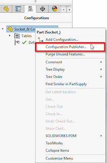
The follow the below steps in making the configuration Publisher. After creating desired configuration in part model, right click on the component name in configuration manger and select the configuration Publisher as shown below.
CONFIGURATION PUBLISHER
When we click the Configuration Publisher, the below Pop-up will be shown. If you didn't create a design table, the Configuration Publisher will auto-create the design table. Click "Yes" to confirm auto create windows as shown below.

CREATING DESIGN TABLE
The configuration Publisher box will pop-up, showing the different properties that can be used to filter through the configurations. That can be dimensions, materials,suppression states & control the attributes, etc.
CONFIGURATION PUBLISHER-ATTRIBUTES CONTROL
You can drag these controls from the left of the configuration publisher panel to middle edit tab, while the edit tab is selected. The process is the same for the Property Tab Builder
APPLY THE CHANGES
After editing is completed, the SW Preview tab will allow the user to view how the Configuration Publisher will display when initiated. When satisfied with the results, make sure to click for Apply for the changes.
PARAMETRES
 DIFFERENT CONFIGURATION NAME
The configuration can still be chosen directly, if desired. When the part/assembly is inserted, the configuration can be chosen from the dropdown bar instead of sorting by properties as shown above.
CONFIGURE PART OR ASSEMBLY
As the parameters are chosen, the part is updated in the graphics area. It helps the user have a visual of which part is being selected before it is chosen. If the chosen configuration needs to be changed and the user can utilize the Configuration Publisher to choose it. For that,right click on Part or Assembly to the Feature manager design tree and then choose configuration part or assembly from the in-context toolbar as shown in the above image.

BENEFITS OF CONFIGURATION PUBLISHER:

Create configurations and share them by automatically uploading your designs to 3D Content Central.It reduces the extra time needed to identify the proper configuration
You can easily edit the parameters of a part/assembly using excel.


STAY TUNED FOR ANOTHER BLOG
THANK YOU FOR READING!


Saturday, 16 May 2020

WHAT WE NEED MORE THAN THIS? - SOLIDWORKS VISUALIZE


What’s the picture tells about? Any guess? Is that Magic Show? Dancing Program? Of course, yes. It is a singing performance.

What’s the thing we shall focus here is “The Lightings”. In discipline, there are several different stage lightings are used. They have experienced light technicians as well as the designers to pull over the audience attention.

Interesting chapter. Isn’t? We are in the connected part with this one to the SolidWorks Visualize. Yes. The Lightings. As we all know SolidWorks Visualize Professional has the core capability of Lighting Tools.

The users now are more enjoyable to have a great tool which is introduced in 2020, “IMPORTING IES LIGHT PROFILES” into SolidWorks Visualize Professional. Keep improving one step ahead. Let see how the workflow is.

Go to Windows-> SolidWorks Visualize-> Model-> Open.
Go to Scenes-> Click + icon to add new Light or simply right click Scenes view port-> add new Light. Then Pick Target/ Pick Position to place where you require.

Then, General Tab-> Click the drop down in Type-> Choose IES Profiles.
It asks for browse location. Click and choose the profiles.

Note: If, in default there is no IES Light Profiles. Please click the following link and free download it. Link: https://leomoon.com/store/shaders/ies-lights-pack/

Once the Profile is browsed, simply choose the Transformation tools and adjust the Light to the position suits to your creativity.
Here are the few samples that IES Profiles achieve in SolidWorks Visualize.
Hope everyone enjoyed. Thank you for your valuable time. Have a try on the tool and get a great exposure and become a light technician/ designer with the help of SolidWorks Visualize. Thank you.


Thursday, 14 May 2020

Enhance Your 2D Drafting Experience to Achieve Best in Class Results Using Draftsight

Latest DraftSight Offerings


DraftSight helps users to create new drawings and access or edit existing DWG files with a strong CAD solution that meets their 2D and 3D DWG file needs. DraftSight provides a far better 2D drafting and 3D design experience for engineers, architects, and construction service providers (AEC), also as professional designers, CAD users, makers and manufacturers. This product is brought to you by Dassault Systèmes, the 3DEXPERIENCE company, and provides flexible offerings for users to choose from:

  •      DraftSight Standard
  •      DraftSight Professional
  •      DraftSight Premium
  •      DraftSight Enterprise
  •      DraftSight Enterprise Plus


DraftSight Standard Capabilities


For individuals who required a straightforward 2D CAD drafting solution with a well- known interface.

  •  Draw tools to make basic elements like lines, polylines, arcs, circles, ellipses, tables, hatches, clouds
  • Modify tools to perform the move, copy, rotate, mirror, pattern, scale, trim, chamfer, split
  • Dimensioning tools to measure distances between objects
  • Layer tools to organize a drawing
  • Blocks to mix a set of entities together into one named object
  • Attach Drawing to feature external regard to the present drawing
  • Print to output a drawing to a plotter, printer or shareable file
  • SVG scalable icons to support high-resolution (4K) clarity displays

DraftSight Professional Capabilities


For professionals and corporations that need a sophisticated 2D CAD drafting solution with powerful, time-saving productivity functionalities and APIs to help bring their designs to life quickly and easily.
  • Toolbox library allows to quickly access generate hardware, holes, balloons, bills of materials, welding and surface finish symbols
  • Batch Printing helps to send a gaggle of drawings and sheets to printers during bulk printing of drawings
  • Drawing Compare tool graphically compare entities between two different drawing documents
  • Power Trim to trim multiple entities, adjacent entities by dragging the pointer across each entity in the viewport
  • G-Code Generator generate codes to talk with a CNC machine for fabrication
  • PDF Underlay to attach pages of a PDF document to a drawing document
  • Macro Recording helps to start out programming and record actions performed interactively within DraftSight interface
  • DraftSight APIs to allows end users to customize and automate the DraftSight functionalities
  • DGN Import allows to import and convert the DGN drawing directly into a DraftSight for direct editing
  • Insert Centerlines to allow selecting two segments and generate a centerline equally in-between
  • Pattern Along a Path to make pattern along with a predefined path entity
  • Split Dimension to create a gap in between dimension lines because when dimensions are intersecting with other drawing entities, it will give even more clarity to the drawing
  • Curved Text to place text along an arc to control the text direction and location even better
  • Hairline to help machines to consume directly .dwg or .dxf file output for laser cutting
  • Image Tracer to convert an imported raster image type file (ex. floor plan, logo) into vectorized line entities to make layout designs
  • Formulas in Tables to support basic formulas in table cell such as sum, count, average, equations
  • Trim Hatch to trim and modify the existing hatch patterns

DraftSight Premium Capabilities


For individuals, designers, makers, manufacturers, professionals, and corporations that require a strong 2D drafting and 3D design experience to assist meet their needs on drafting, modeling, prototyping, manufacturing, laser cutting and 3D printing. It includes all the time-saving productivity functionalities and APIs additionally to the complete 3D tools and constraints capabilities that are exclusive to the Premium version.

  • 3D Modeling tools to make geometrical shapes (ex. Pyramid, Cylinder, Box), more complex 3D objects using Extrude, Loft, Revolve, etc. and to get 3D surfaces with the help of sort of mesh tools
  • Constraints to regulate drawing entities parametrically by specifying geometric and dimensional properties of entities
  • All Professional features that are listed within the DraftSight Professional section

DraftSight Enterprise Capabilities


For large organizations with many users or multiple sites that require a complicated 2D CAD drafting solution with time-saving productivity functionalities and APIs to assist bring their designs to life quickly and easily. It includes complete technical support, deployment and a network license to enable concurrent usage across the organization.

  • All Professional features that are listed within the DraftSight Professional section
  • A network license to enable simultaneous usage and compliance across the organization
  • The Deployment Wizard to enable large groups of users to put in or upgrade DraftSight
  • Full technical support to answer questions or troubleshoot issues associated with DraftSight
This offering can be purchased through a reseller and is out there as Subscription or Non-Subscription (one-time purchase). It runs on Windows with a minimum of two licenses SolidNetWork License (SNL) is required. Should a customer prefer Dassault Systèmes License Server (DSLS) the minimum order is 5 licenses. Email and telephone full technical support are included.

DraftSight Enterprise Plus Capabilities


For large organizations with many users or multiple sites that require a strong 2D drafting and 3D design experience to assist meet their needs on drafting, modeling, prototyping, manufacturing, laser cutting and 3D printing. It includes all the time- saving productivity functionalities, APIs, full technical support, deployment, a network license additionally to the complete 3D and constraints capabilities that are exclusive to Enterprise Plus version.

  • All Premium features that are listed within the DraftSight Premium section
  • A network license to enable simultaneous usage and compliance across the organization
  • The Deployment Wizard to enable large groups of users to put in or upgrade DraftSight
  • Full technical support to answer questions or troubleshoot issues associated with DraftSight
This offering can be purchased through a reseller and is out there as Subscription or Non-Subscription (one-time purchase). It runs on Windows with a minimum of two licenses SolidNetWork License (SNL) is required. Should a customer prefer Dassault Systèmes License Server (DSLS) the minimum order is 5 licenses. Email and telephone full technical support are included.

Stay safe and productive everyone!

For more info, Visit: www.egsindia.com| www.egs.co.in


Wednesday, 13 May 2020

SOLIDWORKS 3D CAD SOLUTIONS


  • In today’s competitive market with the need to produce products faster,with higher, more predictable quality and at lower costs, companies are looking to streamline their workflows.
  • SOLIDWORKS provides the breadth of tools to tackle the most complex problems, and the depth to finish critical detail work. SolidWorks features help you improve your product development process to get your innovative products into production faster.

AVOID REWORKS AND MINIMISE NO. OF PROTOTYPE

  • Identify the errors occur in Assembly within a Design Stage itself.
  • This powerful tool will enhance the Machine Manufacturer to reduce Prototype and its cost.
  • Helps to improve Productivity up to 80% and meet project Timeline.

CLEARANCE DETECTION

  • With Clearance Verification, you can check the clearance between selected components in assemblies.
  • The software checks the minimum distance between the components and reports clearances that fail to meet the minimum acceptable clearance you specify.

HOLE ALIGNMENT 

  • Hole Alignment is feature-based. Alignment is checked for Hole Wizard holes, simple holes, and cylindrical cut features.
  • Hole Alignment does not recognize holes in derived or imported bodies, or multi-boundary extrudes.

INTERFERENCE DETECTION

  • Interference Detection identifies interference between components, and helps you to examine and evaluate those interference.
  • Interference Detection is useful in complex assemblies, where it can be difficult to visually determine whether components interfere with each other.

SMART COMPONENT

  • When you make a component smart, you associate the other components and features with the Smart Component.
  • When you insert the Smart Component into an assembly, you can choose whether or not to insert the associated components and features.


DESIGN AUTOMATION USING MS EXCEL

  • A design table allows you to build multiple configurations of parts or assemblies by specifying parameters in an embedded Microsoft Excel worksheet.

3D DESIGN ANIMATIONS

  • Generate Animations for Machines how it works in real time environment.
  • Share your Machinery animations to your Websites, your Customers and also to Trade Shows etc.

Cost Estimation 

  • The SOLIDWORKS Costing tool helps you calculate how much it costs to manufacture sheet metal, machined, multibody parts, and assemblies as well as plastic molded, cast, 3D printed parts, and multibody weldments by automating the cost estimation and quotation process.

Data Management

  • The SOLIDWORKS PDM® application is project data management software that runs inside the SOLIDWORKS® environment or as a standalone application.
  • Workgroup PDM controls projects with procedures for check out, check in, revision control, and other administration tasks.

Render Images

  • Generating high quality, life-like images and animations is a critical capability that can be used to enhance proposals, presentations, and submissions.
  • People want to see 3D models as they would appear in real life, using specific colors and materials, in a specific environment or setting.
  • They also want to interact, to maneuver around and through the design to gain perspectives impossible in 2D. 

Reverse Engineering Concept

  • Facilitate reverse engineering that can speed up your design process. ScanTo3D reduces the time required to build complex 3D models of real-world items, such as sculpted objects, and anatomical items.
  • 3D data such as point clouds and mesh (which is attained from laser scanners and other devices) can be imported, parsed, manipulated, modified, and ultimately turned into 3D solids and surfaces. 

Schedule a Task- No Manpower is necessary

  • If you need to perform a resource-intensive task such as rebuilding a large assembly, you can use SOLIDWORKS Task Scheduler to perform the job at off-peak hours.
  • You can schedule a task to be performed only once or on a daily, weekly, or monthly basis.

Tolerance Analysis-Assembly Level

  • Tolerance analysis tool used to study the effects tolerances and assembly methods have on dimensional stack-up between two features of an assembly.
  • The result of each study is a minimum and maximum tolerance stack, a minimum and maximum root sum squared (RSS) tolerance stack, and a list of contributing features and tolerances.

Hardware Libraries

  • SOLIDWORKS® Toolbox includes a library of standard parts that is fully integrated with SOLIDWORKS.
  • Select your standard and the type of part you want to insert, then drag the component into your assembly.
  • You can customize the Toolbox library of parts to include your company's standards, or to include those parts that you refer to most frequently.
  • Toolbox supports international standards, including: ANSI, AS, GB, BSI, CISC, DIN, GB, ISO, IS, JIS, and KS.

High and Faster Render Images

  • The fastest and easiest way to photorealistic imagery for anyone that needs to take "photos" of their 3D data. 
  • By utilizing photo-quality content early in the design process, more informed design decisions can be made, as well as receiving useful early feedback from sales teams and potential customers.

Time Based Motion Analysis

  • Easily evaluate how your product will perform and move throughout its operational cycle with motion analysis. Visualize your product moving as it would in the real world and measure the forces and loads on your design.
SOLIDWORKS Motion simulation can calculate the effect of:
  • Forces
  • Springs
  • Dampers
  • Gravity
  • Contact between components
  • Bushings

Piping and Tubing Design

  • Accelerate the development process and save time by designing piping and tubing in 3D during system design with SOLIDWORKS. By integrating piping and tubing during the design process, designers can help ensure efficient assembly, operation, and serviceability, avoiding rework, delays, and extra cost.

Linear Stress Analysis

  • Linear stress analysis enables designers and engineers to quickly and efficiently validate quality, performance, and safety—all while creating their design. Reduce the need for costly prototypes, eliminating rework, and save time and development costs.
Analytical forces can determine such as,
  • Forces
  • Pressures
  • Accelerations
  • Temperatures
  • Contact between components

Electrical Cable Harness and Conduit Design

  • Quickly design and route electrical wiring, harnessing, cabling, and conduit assemblies of products in 3D using the SOLIDWORKS Premium package. Integrating these systems during product design rather than adding them later accelerates your development process, saves time and rework costs, and helps to ensure efficient product assembly and serviceability.

Advanced Surface Flattening

  • Often products like leather goods, sports equipment, footwear, and products made from composite materials, like carbon fiber and fiberglass, have complex shapes, but are manufactured from materials that start out as flat stock, such as cow hides, nylon, cloth, and flat composite sheet.
  • With SOLIDWORKS Premium you can accurately determine or estimate the size and shape of surfaces in their flattened state in order to be able to cut the material from the flat sheet.

Routing of Rectangular and Other Sections

  • SOLIDWORKS Premium users can route rectangular and round sections to meet their design needs. Equipment designers, product designers, machine designers, facility designers and others all need rectangular section routing to complete their designs that include ducting, cable trays, conveyors, material handling chutes, and many other systems.