Saturday, 6 May 2017

Use of Advance Hole For Die Designing Process

SOLIDWORKS provides the Engineers with a Valuable development for mold
designing, with a feature called Advance Hole. This best feature is been brought as an
enhancement in the 2017 version of SOLIDWORKS for creating complex multi diameter holes.
Previously, many features were used in the design interface for making a Single callouts. The
designers had to define the exact callouts in Drawings for manufacturing operation.


The advance hole feature offers designers in customizing holes
within SOLIDWORKS while creating Manifolds & Holes.This feature allows the user to
define hole types with combination of counter bore ,countersink,straight and
tapered selections.


Designers can also indicate Advanced Hole Position using
dimensions, sketch tools, sketch snaps and inference lines. Also, the Advanced Hole
tool provides options to add, update, save, delete or load holes from the Favorites
toolbar.

Benefits

  • Creating Multiple hole in a single operation
  • Provide more consistency between hole designs is a huge time and money
  • saver.
  • Customizing Advance Hole call outs also helps during the manufacturing process.


Thursday, 4 May 2017

SOLIDWORKS 2017 – Feature Delighters

SOLIDWORKS 2017 introduces some great new capabilities that make the design process even more productive. Even the simplest looking design can be visually complex and hard to interpret, due to high amounts of internal detail. SOLIDWORKS 2017 delivers a great new capability for increasing visual clarity, when working in a section view. Now the sectioned geometry of any component or body can be displayed transparent, enabling you to maintain complete visualisation of geometry hidden by the section plane. Using the new property manager option, simply select the components, and set the level of transparency, now it’s even easier to interpret complex designs.


It’s often necessary to have to model the physical Threads on holes and shafts, for applications such as digital simulation and 3D Printing. SOLIDWORKS Thread feature is a great time saver for modelling Threads in one quick and easy to use command. New for SOLIDWORKS 2017, the Thread Feature now provides the option to automatically trim the start and end faces. Plus a new multi start option removes the need for any additional feature patterns, now detailed threads can be created in seconds.


And that’s not all. Now when creating swept features in SOLIDWORKS 2017, in addition to sketch geometry, faces, edges, and curves can now all be used to define the sweep profile. In this example selecting the end face of the thread completely eliminates the extra step of creating a profile sketch for each run out. With SOLIDWORKS 2017 creating swept geometry is now easier than ever. Patterning features has been core part of the SOLIDWORKS modelling toolset from day 1, and is an essential technique for reducing time and effort when creating geometry.


In SOLIDWORKS 2017 creating patterned geometry has got even quicker. Now when creating a Circular Pattern you have the option to pattern in not just one but both directions at the same time. Controlling the second direction is simple using the already familiar spacing options, or just select Symmetric to create a mirrored pattern. Now you can create all the circular pattern geometry you need with far less effort.


With all these great new capabilities, SOLIDWORKS 2017 helps you to reduce your design cycle time without compromising productivity.


Tuesday, 25 April 2017

MAKE GREAT DESIGN HAPPEN WITH EASE OF USE TOOLS

SOLIDWORKS will help Engineers to Design and Validate your product as per the industrial standards and applications. There are some considerations to be done for conducting the best design approach, as follows:


  • Purpose of Design
  • Material of Products
  • Less Weight
  • Should not fail
  • Should not be too costly
  • Following some standards
  • Market survey


Properties to be incorporated for Design Challenges:

Material Library – Applying the mechanical properties for your Design by using a single click Material Library Tab.
Evaluate – Measuring the exact product weight before the manufacturing process for VAVE Optimization.


Material Library
Mass Properties


Static & Nonlinear Analysis – Finding the visual product validation for better performance & quality. Perform a spell check on your designs to ensure the product meets the requirements.

Fatigue Analysis – Predicting the exact design life estimation before the production.


Stress Result
Displacement Result


Costing – By clicking on the Costing feature, provide the estimated cost before proceeding the manufacturing process. The estimated cost can be a comparison for Gain/Loss challenges in giving a better design comparisons.


Visualize – Make your designs to be viewed as a real time product before the manufacturing stage. The realistic images can provide the designers to give the detailed information for the aesthetic looks.


SOLIDWORKS Solutions for Sales & Marketing

E-DRAWING

  • Handle 2D & 3D design data, anytime, anywhere
  • View, Zoom, pan, rotate, section and virtually disassemble
  • Measure, mark up, comment, stamp, re-order views
  • Password Protect Intellectual Property
  • Win Business through Effective Communication


COMPOSER


  • Clearly explain and present your product or process using 2D and 3D graphical content
  • High quality illustrations, photorealistic images and interactive animations to enhance Product Sales
  • Technical communication that helps customers and partners understand and retain product information
  • Import design data to create bills of materials (BOMs), add dimensions, place surface finish labels, and so on.


VISUALISE

  • Improve internal design, engineering, and sales reviews to help make more educated final decisions
  • Drastically reduce the cost and number of physical prototypes
  • Deliver photorealistic imagery and content to marketing much earlier to help promote the newest products via web/print
  • Added time savings allow for more design time, which results in an overall better final product


COSTING


  • Easily monitor manufacturing costs as you design, thereby avoiding costly redesigns and production delays later on
  • Automatic Manufacturing Cost Estimation and Quoting/Design for Cost
  • Customize costing inputs based on company and regional conditions
  • Assembly Cost Roll Up


Friday, 31 March 2017

Design Work Stopped when Simulation Analysis is Running? Doesn't Matter with this New Feature in SolidWorks Simulation

The What's New 2017 proved with a good set of enhancements for User post processing. One such enhancement is the Off-loaded Simulation in solving the analysis studies. User faces problems related to time consuming process when a large problem is setup for study. This off-loaded simulation enhancement allows the analyst to solve the setup studies on another computer. The introduced enhancement for 2017 is available for SolidWorks Simulation Premium licences, which can be used for Static & Non Linear setup studies.


Steps involved:
  1. Identifying another computer to free up resources for parallel tasks from the user involved system
  2. Solution is run on another computer connected on the same network domain
  3. Coordinator system requires SolidWorks & Simulation Premium license. SolidWorks Simulation Worker Agent to be installed & activated on the network connceted system
  4. Create Static or Non Linear studies on the coordinator machine
  5. Temporary results saved on the other system when the analysis is run
  6. Post processing results viewed in the coordinator system after the analysis is run

Installing SolidWorks Simulation Working Agent
  1. Install & launch the Simulation Worker Agent Program on the network attached computer
  2. Include the SolidWorks Installation files & run the setup on the client machine
  3. In the Summary page during the installation process, in the products Tab, click on "Change"
  4. Select the SolidWorks Simulation Worker Agent for installation process
  5. Launch the Simulation Worker Agent application after the installation process is done
  6. Click on Activate Worker Agent to enable the Status information set to Idle Status

To setup & manage the network simulation, click on the Offloaded Simulation in the coordinator system & manage the network manager to enable the connected network system. During the analysis process, the Intel Network Sparse Solver available for this enhancement in automatically enabled. Under this process, the User is liable to select the corresponding machines for coordinator & for the client machine.

Benefits
  • Time reduction during the validation process
  • Multi tasking design process
  • Free up resources for analysis result files
  • Easy approach for post-processing results


Thursday, 23 March 2017

SolidWorks Drawing - Linking Note To Table Cells

We all know that note are an important part of any engineering drawing and help to transfer vital information. One of the problems when dealing with drawings is to keep these note up to date. The best solution for that problem is to automate the process and ask the software to take care of maintaining them. That is what SOLIDWORKS keeps doing every year.

For example:
1. In 2016 what’s new SolidWorks added a facility of linking a note to balloons using a flag note.
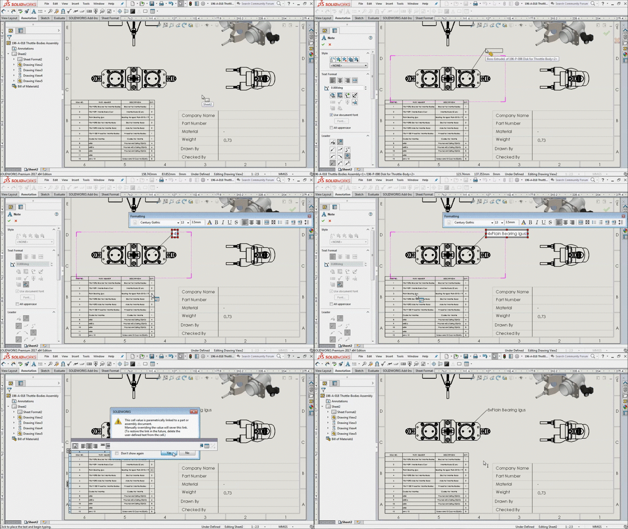
2. In 2017 what’s new SolidWorks added enhancement in note, now we can directly link a note to the content of an table cells.


How to link a note to table cells:
The following steps will explain how to link note to table cells.
1. Click note, from Annotation tab.
2. Place the text in graphical area of sheet.
3. Click “Link Table Cell” from Note property dialog > Text Format.
4. Now select the cells from table which we want to link with the note.


The below images will explain the method
Linking note to BOM table
Linking note to Weldment table
Linking note to Hole table

Note:
1. We can also link note to multiple cells in single annotation.
2. If a change occurs to the table cell, either automatically or through manual editing then the note will update automatically.

For example:
1. Fasteners of part number either use material brass or stainless steel can easily link to table cells.
2. Structural member part number whose length can easily link to table cells.
3. Holes of the part refers to the standard size can easily link to table cells.