Thursday, 3 April 2025

How to Use Advanced Select Options in SOLIDWORKS?

In SOLIDWORKS, when working with large assemblies that include multiple subassemblies, selecting individual components can become a significant challenge. The standard method of selecting components from the Feature Manager design tree can be inefficient, as it often includes subassemblies, making it difficult to isolate and select the desired parts.

This blog will explore the challenges of selecting components in large assemblies and introduce the concept of using a selection tool to streamline the process. By utilizing advanced search techniques, you can efficiently select all parts within an assembly, whether they are in the main assembly or nested within subassemblies. This approach helps improve efficiency, especially when dealing with large and complex assemblies in SOLIDWORKS.

Advanced Select in SOLIDWORKS

SOLIDWORKS allows users to select components based on their properties using the built-in selection options. For example, it offers the ability to select all suppressed parts with a single click. Additionally, users can define custom search criteria by specifying conditions and values and can apply logical “and” or “or” operators between these criteria.


Category 2 can be defined for specific options within Category 1, including custom properties, in-context relations, and file status. When these categories are selected, Category 2 displays the relevant parameters or options that can be used for selection. The available conditions for filtering in SOLIDWORKS include ‘=’, ‘<+’, ‘<‘, ‘>’, ‘>=’, ‘≠’, ‘contains’, ‘is (exactly)’, ‘is not’, ‘is inside’, and ‘is outside’. This flexibility allows for more refined and tailored selections, streamlining the design process.

Refining Component Selection in SOLIDWORKS

In the context of SOLIDWORKS, efficiently selecting specific components within an assembly is crucial for streamlining workflows, especially when applying properties such as materials. A common scenario is the need to select all parts in an assembly while excluding subassemblies. This can be particularly useful when you want to apply material to every part simultaneously.

One effective method to accomplish this is by utilizing SOLIDWORKS’ advanced selection tool. By defining a custom search criterion, such as the “Document Name – SW Special” category, you can refine the selection process. For example, by setting the condition to “contains” and the value to “.sldprt” (the file extension for part files), you can specifically select all part documents within the assembly. This approach ensures that only part files are selected, leaving subassemblies untouched.

SOLIDWORKS

Additionally, SOLIDWORKS allows you to save this custom search as a predefined selection filter. Once saved, you can add it to your list of favorites, making it easily accessible whenever you right-click and need to perform similar selections in the future.

This is just one of the many practical applications of advanced selection techniques in SolidWorks. Whether you’re dealing with large assemblies or complex designs, these tools can be tailored to meet a wide variety of selection needs, improving efficiency and accuracy in your modelling process.

ADVANCE SELECT OPTIONS In SOLIDWORKS

Another commonly used selection option in large assemblies is the ability to select internal components for suppression, which helps improve overall assembly performance in SOLIDWORKS.

SOLIDWORKS

Imagine manually selecting each internal component to suppress them – it could take a lot of time. However, as shown in the performance evaluation tab, we were able to suppress 748 components with just one click, saving a significant amount of time in SOLIDWORKS.

SOLIDWORKS

Thank you for reading! I appreciate your time and hope you found the insights helpful.

Author: Nandhakumaran is an Application Engineer at EGS India, a SOLIDWORKS Value-Added Reseller, with expertise in Dassault Systèmes software across multiple industries. With over 20 certifications in SOLIDWORKS and Dassault Systèms software, He is dedicated to helping clients get the most out of their tools.

Contact Us: Have questions or need assistance? Feel free to reach out!

Email: mktg@egs.co.in
Phone: +91 94454 24704


SOLIDWORKS Simulation - Global Interactions (Bonded) with & without gap range

 Usually, there won’t be any problems with the process once the user begins to simulate a part to get the results. The question arises on the interaction of components where the user tries to work with assembly. The observations are most probably that they have either removed their global interaction or altered the gap range of bonding.

There are three types of Interaction in the Component Interaction command window. In this blog the bonded interaction with & without gap range is discussed in detail


  1. Bonded: This defines two faces touching each other or faces with a specific gap range between them (When specified for non-touching faces) to stay remained touching irrespective of loads applied on the faces during analysis. When two parts with two faces are bonded together they behaves as one part.
  2. Contact: This defines two or more faces to touch and develop interaction between them, as well as move away from each other. There will be a small gap range between two faces for their reaction when forces are applied.
  1. Allow Penetration: This interaction feature enables many components to flow into each other at the defined faces while the analysis is running. This interaction option is mostly utilized for frequency and buckling analysis.

The Gap range of bonding represents the value/percentage of gap between the parts in the assembly. This value makes the interaction of components possible with gaps while simulating an Assembly.

Component Interaction Types:-


Assembly Considered for Simulation without gap (Case 1):-


Assembly Considered for Simulation with gap (Case 2):-


Boundary Conditions:-
All the four legs were fixed & 100 N of load/Force is acting on the table.


Interaction Conditions:-
The interaction condition of the two cases are important to replicate the behaviour of the assembly. In case 1 the assembly has no gap when the model is considered for simulation it automatically takes the component interaction as bonded as far as SOLIDWORKS Simulation is considered, but in the case 2 the scenario is different because of gap. Interaction viewer

Assembly with gap (No geometry based Interaction found)

Assembly with gap (With gap range as 6mm)


In case 2 the assembly has a maximum gap of 6mm in the model, so the gap range to be mentioned in the component interaction so that the interaction can be generated. After solving the assembly there behaviour of the results are discussed here.

In case 1 the behaviour is common but in case 2 there are two different behaviour in the results because of gap range.

When the gap range is mentioned as 0mm the results behaviour changes drastically, and if the value is mentioned as 6mm (large gap value) the result behaviour matches with the first assembly.


Results:

 -  Assembly without gap range 

 - Assembly with gap & with gap

 Assembly with gap without gap range

Author : Karthikeyan R is an Application Engineer with an under graduation degree in Mechanical Engineering (B.E), specialization in Product Design & Manufacturing (M.TECH). He serves as a Technical Support Engineer – CAE Applications, with year of Academic experience & 2.5 years of experience over SIMULIASOLIDWORKS SIMULATION and also with the 3DEXPERIENCE Ecosystem. His expertise has enabled him to successfully assist over 50 customers in resolving technical challenges, improving their Product development, and achieving their goals.

Contact Us: Have questions or need assistance? Feel free to reach out!

Email: mktg@egs.co.in
Phone: +91 94454 24704


What Are the Best File Utilities for SOLIDWORKS File Management?

 SOLIDWORKS File Management is the process of efficiently handling and organizing files for ease of use and accessibility. However, managing CAD files can be challenging and may not align with our preferred working methods.

The aim of this Series is to learn effective methods for organizing SOLIDWORKS File Management in a way that enhances your workflow and improves file management efficiency.

Let’s Begin with SOLIDWORKS Files
SOLIDWORKS CAD FILES vs OTHER FILES

What is the difference between SOLIDWORKS CAD FILES over other files?

For example, let’s take an Excel file for understanding.

Excel File:
 
An Excel file structure is a single-point database, meaning each piece of information is stored in a single file.

SOLIDWORKS Files:
 SOLIDWORKS File Management
 consists of three main components:

  1. Header
  2. Instruction Set
  3. Database

Header:
 
This header contains information about the file, such as file name, file type, file format, and file properties.

Instruction Set:
 
The instruction set provides details to build the model, including features and sketches, or we can say it’s a binary form of the feature manager design tree.

Database:
 
The database contains the topological definition of the solid body.

This is the basic structure of SOLIDWORKS files, but it can vary with file formats.

Unlike Excel files, which can be easily saved without references, SOLIDWORKS files have references to other files for proper functionality. To work effectively without breaking references and to help organize files efficiently, SOLIDWORKS introduces File Utilities. This tool is mainly designed to manage and handle file references, making SOLIDWORKS File Management more efficient.


Note:

Till SOLIDWORKS 2019 SP 5.0, SOLIDWORKS Explorer was a separate software application. However, after 2019, SOLIDWORKS Explorer was integrated into File Explorer and is now called SOLIDWORKS File Utilities.

You can see this during the installation of SOLIDWORKS software in the product selection page or when modifying SOLIDWORKS software.

SOLIDWORKS FILE UTILITIES
Where to Find It?

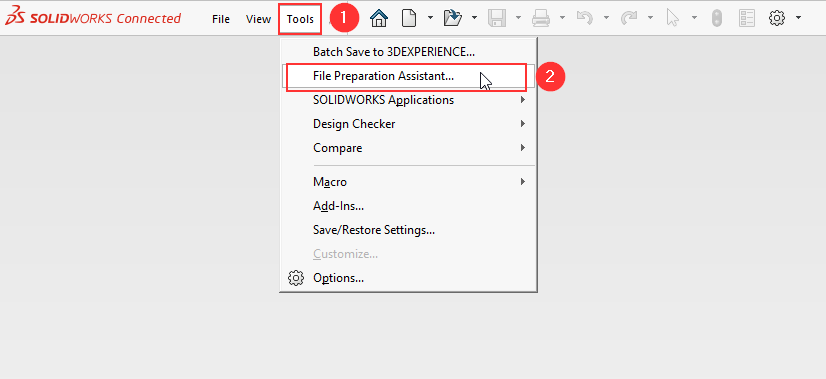
SOLIDWORKS File Management tools can be accessed by right-clicking on a SOLIDWORKS file, where you will find the SOLIDWORKS options in the context menu.

Options Available in SOLIDWORKS File Utilities

Using SOLIDWORKS File Management, you can perform the following actions:

  • Open
  • Pack and Go
  • Rename
  • Replace
  • Move
  • File Location
Rename and Move
What Happens When You Rename and Move Files Using Normal File Explorer vs. SOLIDWORKS File Utilities?

File Explorer

SOLIDWORKS File Utilities

Step 1: Right-click a SOLIDWORKS file used in an assembly, cut, and paste it to another location.

Step 1: Right-click a SOLIDWORKS file used in an assembly, select SOLIDWORKS, and click Move. A dialog box appears.

Step 2: Open the main assembly and notice missing references.

Step 2: Choose the exact location to move using the Browse option.


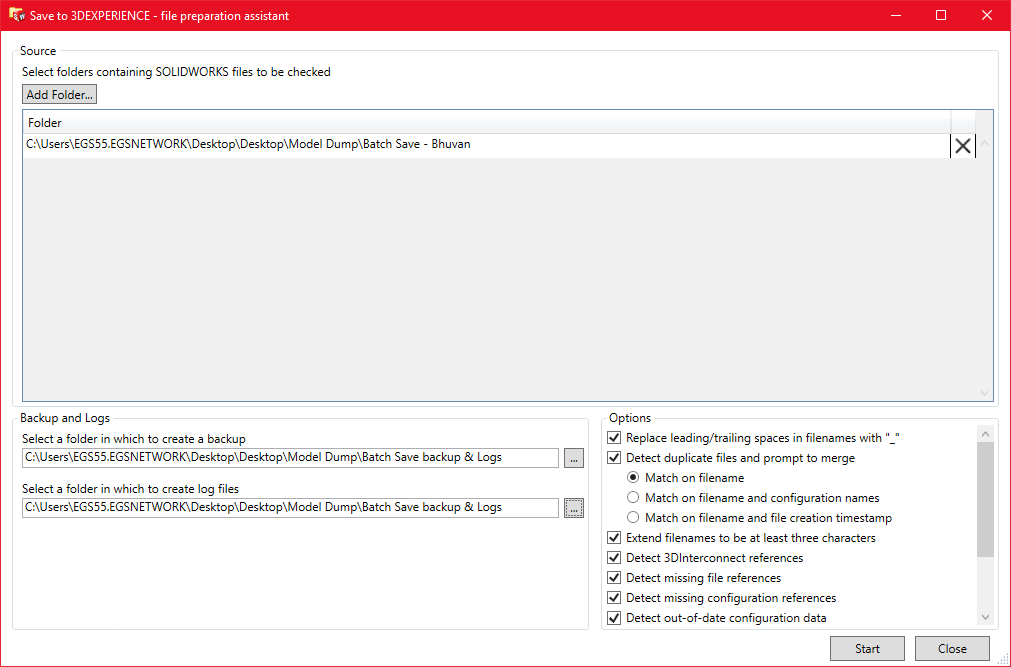
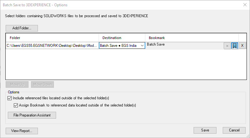
Pack & Go and Replace

Using SOLIDWORKS File Management, the “Pack & Go” and “Replace” options allow you to manage files without opening SOLIDWORKS. These options function the same way as the in-app Pack & Go tool.

  • The “Replace” option allows you to replace components without opening SOLIDWORKS, functioning similarly to the move process.

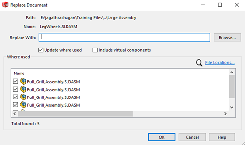
Click Browse to choose a replacement component, enable “Update Where Used,” and click OK to replace the component in the assembly.

FILE LOCATION

The “File Location” option is used to find the assemblies that used by the specific component. When the component was last saved, it will not map the file references but will display the path and the assemblies in which the component is used, but it will search only user added location in file location option.


Click file locations in the context menu, one dialog box will open add prefer location for your search.

Note: The “Include Subfolders” option should be enabled, as this will allow the search to extend into the subfolders within the main folder.

Author: Jagathrachagan A is an Application Engineer with a background in mechanical engineering. He specializes in providing solutions for customer queries and technical issues. He is dedicated to helping users tackle complex design challenges by offering training and timely guidance, empowering them to effectively use the software to meet their specific needs.

Contact Us: Have questions or need assistance? Feel free to reach out!

Email: mktg@egs.co.in
Phone: +91 94454 24704


Wednesday, 2 April 2025

How to Boost Productivity with Batch Save in 3DEXPERIENCE SOLIDWORKS?

 Managing large assemblies and complex projects in SOLIDWORKS can be time-consuming, especially when it comes to saving multiple files to the 3DEXPERIENCE platform. The Batch Save in 3DEXPERIENCE SOLIDWORKS functionality simplifies this process, saving you valuable time and ensuring data consistency.

What is Batch Save in 3DEXPERIENCE SOLIDWORKS?

Batch Save in 3DEXPERIENCE SOLIDWORKS is a powerful feature within the platform that allows users to save multiple files (parts, assemblies, drawings) to the platform in a single operation. It helps manage file relationships, updates revisions, and ensures all dependencies are uploaded properly.

Why Use Batch Save in 3DEXPERIENCE SOLIDWORKS?
  • Time Efficiency: Instead of saving files one at a time, Batch Save in 3DEXPERIENCE SOLIDWORKS automates the process.
  • Data Integrity: Ensures linked files (e.g., assemblies and their referenced parts) are saved together to avoid missing references.
  • Streamlined Collaboration: Allows teams to access the latest versions of all files on the 3DEXPERIENCE platform.
  • Minimized Errors: Avoids forgetting to save critical files or breaking references in assemblies.
Pro Tips for Effective Batch Save in 3DEXPERIENCE SOLIDWORKS

Before uploading any models into the platform, it’s recommended to analyze the data to detect or correct any issues. To help with detecting a large data set, File Preparation Assistant is available within SOLIDWORKS.

To access: Go to Tools > File Preparation Assistant.


File Preparation Assistant helps us to detect and correct the following:

  • File names with leading/trailing spaces (Replaces with “_”)
  • Duplicate file names (Provides ability with options for merging)
  • Extend file names to include at least three characters
  • Detect 3DInterconnect references
  • Detect missing file references
  • Detect missing configuration References
  • Check custom property values for consistency

To check all the above points, enable them in the File Preparation Assistant dialog box as mentioned below.


How to Use Batch Save in 3DEXPERIENCE SOLIDWORKS

Once all the checks are done and files are ready for upload, we can start the Batch Save in 3DEXPERIENCE SOLIDWORKS. By default, the Batch Save in 3DEXPERIENCE SOLIDWORKS add-in is enabled. If not, go to Tools > Add-Ins and enable it.

  1. To open the batch save tool in SOLIDWORKS, click Tools > Batch Save to 3DEXPERIENCE.
  2. Click Add Folders, navigate to the folder, and select all the necessary folders to be uploaded. (Navigate to the top-level root folder containing the files you want to save.)
  3. In the destination option, select the Collaborative Space in which files need to be uploaded, and select the Bookmark as well. If needed, a new Bookmark can also be added from there.


    1. Click Move Up & Move Dowto change the order of the folders based on the priority to upload.
    2. To ensure that you are gathering all documents related to the model, under Options, clickInclude referenced files located outside of the selected folder(s).
    3. The Include referenced files located outside the selected folder option includes all the referenced files that are placed outside the selected folder for the save process. Also, these files are added in the selected bookmark if Assign Bookmark to referenced data located outside selected folder option is selected.
    4. After all the options are selected, click Save to run Batch Save in 3DEXPERIENCE SOLIDWORKS.
    5. We can also click View Report to see the details of the uploaded document and status.

    Note: Since this is an asynchronous approach, it allows you to continue using SOLIDWORKS. You can work only on those files that are not in the scope of the ongoing save operation.

    Author: Bhuvan Kumar A, is a seasoned Elite Application Engineer with extensive experience in SOLIDWORKS Portfolios and cutting-edge product design solutions. With a career spanning over 5 years, specializes in empowering teams to deliver innovative, high-quality designs through advanced CAD & PLM tools. Having worked on diverse projects in industries to brings a deep understanding of complex engineering challenges and how to overcome them with scalable, collaborative tools like 3DEXPERIENCE, PDM.

    Contact Us: Have questions or need assistance? Feel free to reach out!

    Email: mktg@egs.co.in
    Phone: +91 94454 24704


How Can Equations Automate Design Processes?


Equations: Automation in Design Processes​


In today’s competitive world, the industries are constantly looking for ways to streamline their processes. Whether it's manufacturing, product development or design, saving time directly translates to saving money. One of the most effective ways to achieve this is through Automation.
In the Design world, automation lets you capture and reuse engineering knowledge and design intent. The benefits of automation in design processes are numerous:

  • It minimizes manual intervention, reducing errors.
  • It enhances efficiency by making design updates seamless.
  • It improves dimensional accuracy across revisions.
  • It maintains design intent across multiple iterations, and so on.

Within the design process, automation in SOLIDWORKS plays a vital role in achieving these goals. One powerful way to automate tasks is by using Equations, which create relationships between dimensions and allow changes to propagate automatically.

Equations:


In SOLIDWORKS, equations are simple yet powerful tools that allow you to automate complex design relationships. By defining mathematical relationships between dimensions, you can ensure that every component of your design adapts automatically to changes. This eliminates the need for repetitive manual adjustments and ensures the consistency of your design intent.

To fully utilize equations, it's essential to understand the Equation Dialog Box in SOLIDWORKS. This tool provides an interface where you can define and manage equations, Global Variables, and Features. Let’s dive into the components of the Equation Manager and their functionalities.

Equations Dialog Box:
The Equation Manager is an intuitive interface that enables you to manage all equations and relationships in your design. It can be accessed by navigating to  Tools > Equations or by clicking the Equation icon from the Feature Manager Tree. The dialog box is divided into three primary sections:


1. Global Variables Tab
This section is dedicated to creating reusable variables that act as parameters across your model. Allows you to define key values (e.g., Thickness = 10mm, Length = 200mm) that can be used throughout your equations and dimensions. It is used to standardize frequently used parameters within your model.

2. Dimensions/Features Tab
This section lists all dimensions and features associated with equations. It also provides advanced functionality for controlling the behaviour of your features. It allows you to directly associate equations with specific dimensions or suppress features based on logical conditions. It is used to control specific feature behaviors in the model.

3. Equations Tab
This is where you define the relationships between dimensions using mathematical formulas and logical operators. Allows you to link dimensions with formulas, ensuring they adapt dynamically to changes. It also supports advanced calculations using mathematical functions (e.g., SIN, COS, TAN) and conditional logic (e.g., IF/THEN statements). It is used to create dependencies between different features or components.

Additional Features in the Dialog Box

  • Filter/Search Bar: Quickly find specific equations, variables, or features.
  • Equation Preview: Displays the evaluated result of each equation in real time, helping to verify logic.
  • Error Checking: Highlights any invalid equations or missing references to help troubleshoot issues.

This structured interface makes it easy to organize complex relationships and automate the behaviour of your design.

Equations in Part Files
Equations, combined with global variables in parts enable you to create smart, parametric models that adapt dynamically to design changes. While equations establish relationships between dimensions, global variables allow you to define reusable parameters that can be shared across features. This combination ensures consistency, accuracy, and automation in part modelling.

An example would be to set a global variable for tolerances and can be used anywhere within the file. Mathematical expressions can be added easily that enables us to enter complex functions without having to them. Another example that we can look at is a gear, where the module and the number of teeth is global variables. We shall take a look at how the equations are set up for this particular case, and the automation achieved through this set up.


Here we can see that the Module and Number of teeth are entered as global variables, and the pitch circle, the height of the teeth, the hole diameter are all driven through with the global variables. By changing only the number of teeth or the module, the gear updates all the required values while holding on to the intent it was designed with.


Setting up equations can be done without the use of the equations dialogue box by typing an equal sign when entering the value for dimensions. You Automatically see the global variables that is present in the file, and the functions and file properties available.


Equations in Assemblies
In assemblies, equations and global variables allow you to create intelligent relationships between components. This is especially useful for synchronizing parts and maintaining consistent design intent across an entire assembly. By referencing global variables or dimensions from other components, you can automate the design process and adapt quickly to changes.


One example would be to add clearance as a global variable. In a shaft-and-hole assembly, clearance ensures proper fitting by preventing interference. Using equations, you can automate the relationship, such as setting the hole diameter to always be Shaft Diameter + Clearance. This guarantees the assembly adjusts dynamically with size changes, maintaining consistent functionality and eliminating manual recalculations during design updates.

Another example would be to link patterned parts. In a gripper assembly, the actuating cylinder connects to a holder plate with N flanges, where each flange supports a gripper finger. By linking the number of flanges (N) to the gripper fingers using equations, the assembly dynamically updates the number of fingers and flanges when N changes, ensuring automation and consistency. Another approach for the same would be to link the equations together, that they hold the same value at all times. We’ll take a look at it now and see what benefits it possess.


In conclusion, equations in SOLIDWORKS are not just a tool—they’re a gateway to smarter, faster, and more efficient design. From automating clearances in assemblies to dynamically adjusting part features like gear teeth or gripper components, equations simplify what was once a tedious process. They reduce errors, enhance collaboration, and bring unparalleled consistency to your designs.
The benefits are clear: faster iterations, fewer mistakes, and more room for innovation. Let’s start integrating equations into your projects today and experience the full potential of intelligent design.

Contact Us:   Have questions or need assistance? Feel free to reach out!

Email: mktg@egs.co.in
Phone: +91 94454 24704