DESIGN TABLE:
Design tables are a way to create different parts or assembly configurations by defining parameters in cells, rows, and columns of an integrated Microsoft Excel spreadsheet.
NOTE: To use design table, must have Microsoft Excel 2016-2021 on computer for SOLIDWORKS 2022-2025.
Desing table for part:
1. Used to edit any dimensions of a 3D part.
2. Also used to create multiple configurations of the same part.
3. These configurations can use complex equations in the design table to
achieve any desired outcome.
STEP 1: Creating a part
A part is created using SOLIDWORKS. For example.
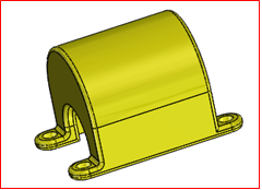
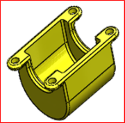
Figure 1
Specific name has been mentioned to define the dimensions on the design table.
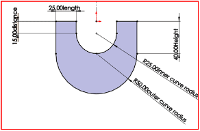
Figure 2
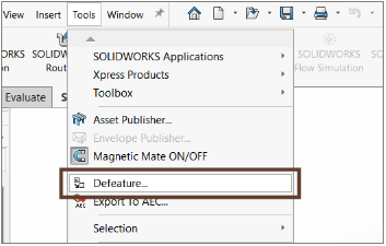
STEP 2: creating design table
To create design table the following commands are used
- Menu bar: Insert –> tables –> Excel Design table
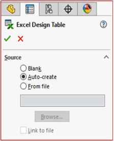
Figure 3
On following the above steps, on property manager source, edit controls, options are displayed as shown below. By default, some options are selected and on source the auto-create is selected, which creates an auto design table with reference to the model that created. Click .
STEP 3: Dimensions, features
On Clicking the Auto-create option, design table has been created. The Dialog box opens where user can select from the following dimensions to add in this new design table.
Click OK.
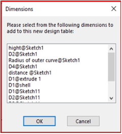
Figure 4
Selected dimensions are loaded to the design table.
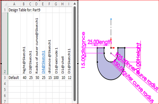
Figure 5
STEP 4: Changing dimensions, features
Changes that made in the design table also changes the feature, dimension and fillets. In this the D1@fillet1 radius and the D1@Bossextrude4 is modified.
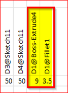
Figure 6
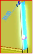
Figure 7
STEP 5: Adding configuration and materials
1. We can add materials and configurations to the design table to reflect it on design.
2. When adding the new configuration, the dialog box gives the information that the design table as created new configurations.
3. New1, New2 are the configuration created on design table.
4. Material of the part can be changed / modified in the design table using the drop-down box.
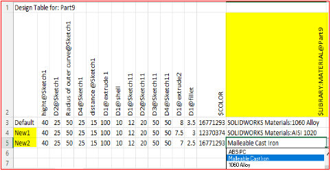
Figure 8
After saving the above table automatically, the dialog box appears with the information of the new configurations that are created as shown below.

Figure 9
The design table for the part has been created. From the design table we have created the configuration table.
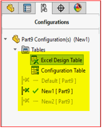
Figure 10
Author : Sudhakar R
Application Engineer | Mechanical Engineering Specialist with nearly two years of hands-on experience, I specialize in SOLIDWORKS CAD and the 3DEXPERIENCE Design Ecosystem. My journey has allowed me to support over 100 customers, assisting them with product design, drafting, and 3D modelling using advanced CAD techniques. I also conduct training sessions and provide ongoing support to engineers, designers, and cross-functional teams, ensuring they optimize their use of SOLIDWORKS and follow best practices. I’m passionate about helping others unlock the full potential of their design tools and creating efficient workflows.
Contact Us: Have questions or need assistance? Feel free to reach out!
Email: mktg@egs.co.in
Phone: +91 94454 24704