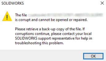
Nowadays, many people struggle or affected by SOLIDWORKS file corruption, yet they often fail to identify the causes behind it and continue to repeat the same mistakes. The main goal of this document is to avoid SOLIDWORKS file corruption by outlining the possible reasons for it.
The main reason for SOLIDWORKS file corruption is where you save your file. Now immediately go check the saving location for your SOLIDWORKS CAD file If it’s saved on your computer’s local drive, that’s okay. But if it’s saved on a network drive, shared folder, or a server, the chances of file corruption are higher.
Now, I’m sure you have many questions in your mind, and I’ll answer the main question you’re thinking of.
Question N0:1 Since we all work with file collaboration; how can we save and work on a local drive? And why does working with a network drive or shared folder cause file corruption?
Working with a network drive or shared folder doesn’t cause file corruption. However, saving, opening, or working with SOLIDWORKS files directly on a network drive can lead to file corruption. Let me explain in more detail. First, watch this video where I have an assembly located on both a network drive and a local drive. I will open the assembly and compare the opening times for both the local drive and the network drive.
When opening a file from a network drive, several factors must be considered between the client and server. These include network bandwidth, current network traffic, drive capability (such as HDD or SSD), antivirus scanning, and network settings. All these processes run in the background, whereas local files are easily accessed by SOLIDWORKS.
Saving SOLIDWORKS files on a server or network drive not only affects the file opening speed but also impacts working speed. For example, when working with an assembly in Lightweight mode, SOLIDWORKS loads only the solid and surface data. However, when switching to Resolved mode, it retrieves the feature history, leading to latency issues. Additionally, sudden network disconnections or slow bandwidth increase the risk of file corruption.
A simple workaround for saving files on a network drive is to first copy the file from the server to the local drive using Windows Explorer. Then, work on the file locally, save it, and finally paste it back onto the server or network drive via Windows Explorer. For instance, when copying an assembly file of 600KB using Windows Explorer, it takes 18 packets of 32KB each. However, opening it directly through the application results in 150 packets of 4KB each. Therefore, to avoid file corruption and improve performance, it is recommended to save and work on files locally.
Question N0:2 I have Microsoft documents like Excel and PDF are working fine with the server, but why SOLIDWORKS files are get corrupted?
SOLIDWORKS files are interlinked, for example, when you save a SWX drawing file to the server, it will reference all associated files such as the assembly file, part file, and subassemblies. These files are saved together, making it large binary data. If there is any connectivity error during this process, it can lead to file corruption.
MAKES YOUR DESIGN WITHOUT ANY ERROR
A secondary reason is to ensure that your design is free from errors. If your file becomes corrupted, it can be difficult to identify the corrupted file errors and warning files. Therefore, it is important to work with minimal errors to avoid such issues

PARTH LENGTH
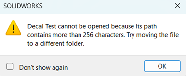
When saving a SOLIDWORKS file, the file path should not exceed 256 characters. This applies not only SWX files, all files saved in Windows. To avoid issues, maximum reduce file saving path and special characters in file names.
OTHER FACTORS AFFECTING SWX FILE CORRUPTION:
- Sudden power loss.
- Connectivity issues during file saving or while working with a server or common sharing.
- Check folder permissions on the server.
- Errors when copying files due to system errors or user termination.
- Avoid creating assemblies with numerous imported files.
- Antivirus protection: If an antivirus blocks file saving to the server, it may cause file corruption. To prevent this, add exceptions for your working directory and the SOLIDWORKS .exe file.
SOLIDWORKS PDM:
If you want file collaboration and need to work with a server while avoiding these issues, SOLIDWORKS offers a product called SOLIDWORKS PDM (Product Data Management). It features a powerful tool called ‘check-in’ and ‘check-out.’ When you check out a file from the server, it copies all associated files to your local drive (as temporary files). Any changes you make will be saved locally. Only when you check the file back in will all the updated information be saved to the server. For more information about this product, feel free to reach out to us.
Contact Us: Have questions or need assistance? Feel free to reach out!
Email: mktg@egs.co.in
Phone: +91 94454 24704


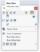
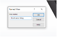

 5. Confirm the update.
 This ensures that your model is always displayed in the most practical orientation for your workflow.